512Mb, 3V Multiple I/O Serial Flash Memory
Features
Micron Serial NOR Flash Memory
3V, Multiple I/O, 64KB, Sector Erase
MT25QL512AB
Features
Options
• Voltage
– 2.7–3.6V
• Density
– 512Mb
• Device stacking
– Monolithic
• Lithography
– 45nm
• Die revision
• Pin configuration
– RESET and HOLD#
• Production status
– Engineering samples
• Operating temperature range
– From –40°C to +85°C
– From –40°C to +105°C
• Special options
– Standard
– Automotive
• Standard security
• Packages – JEDEC-standard, RoHScompliant
– 16-pin SOP2, 300 mils
(SO16W, SO16-Wide, SOIC-16)
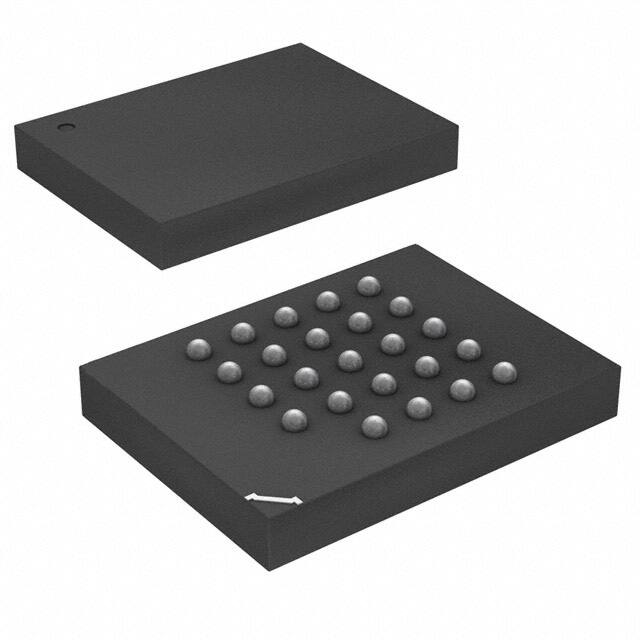
– 24-ball T-PBGA 05/6mm x 8mm
(TBGA24)
• Sector Size
– 64KB
• SPI-compatible serial bus interface
• Single and double transfer rate (STR/DTR)
• Clock frequency
– 133 MHz (MAX) for all protocols in STR
– 66 MHz (MAX) for all protocols in DTR
• Dual/quad I/O commands for increased throughput up to 65 MB/s
• Supported protocols in both STR and DTR
– Extended I/O protocol
– Dual I/O protocol
– Quad I/O protocol
• Execute-in-place (XIP)
• PROGRAM/ERASE SUSPEND operations
• Volatile and nonvolatile configuration settings
• Software reset
• Additional reset pin for selected part numbers
• 3-byte and 4-byte address modes – enable memory
access beyond 128Mb
• Dedicated 64-byte OTP area outside main memory
– Readable and user-lockable
– Permanent lock with PROGRAM OTP command
• Erase capability
– Bulk erase
– Sector erase 64KB uniform granularity
– Subsector erase 4KB, 32KB granularity
• Security and write protection
– Volatile and nonvolatile locking and software
write protection for each 64KB sector
– Nonvolatile configuration locking
– Password protection
– Hardware write protection: nonvolatile bits
(BP[3:0] and TB) define protected area size
– Program/erase protection during power-up
– CRC detects accidental changes to raw data
• Electronic signature
– JEDEC-standard 3-byte signature (BA20h)
– Extended device ID: two additional bytes identify
device factory options
• JESD47H-compliant
– Minimum 100,000 ERASE cycles per sector
– Data retention: 20 years (TYP)
PDF: 09005aef84fe19ac
qlks_512mb_3V_45nm.pdf - Rev. C 12/13 EN
1
Marking
L
512
A
B
A
8
ES
IT
AT
S
A
0
SF
12
E
Micron Technology, Inc. reserves the right to change products or specifications without notice.
© 2013 Micron Technology, Inc. All rights reserved.
Products and specifications discussed herein are subject to change by Micron without notice.
�512Mb, 3V Multiple I/O Serial Flash Memory
Features
Part Number Ordering
Micron Serial NOR Flash devices are available in different configurations and densities. Verify valid part numbers
by using Micron’s part catalog search at www.micron.com. To compare features and specifications by device type,
visit www.micron.com/products. Contact the factory for devices not found.
Figure 1: Part Number Ordering Information
MT 25Q L
xxx
A
BA
1
E
SF - 0
IT
ES
Production Status
Blank = Production
ES = Engineering samples
QS = Qualification samples
Micron Technology
Part Family
25Q = SPI NOR
Voltage
L = 2.7–3.6V
U = 1.7–2.0V
Operating Temperature
IT = –40°C to +85°C
AT = –40°C to +105°C (Grade 2 AEC-Q100)
Density
064 = 64Mb (8MB)
128 = 128Mb (16MB)
256 = 256Mb (32MB)
512 = 512Mb (64MB)
01G = 1Gb (128MB)
02G = 2Gb (256MB)
Special Options
S = Standard
A = Automotive quality
Security Features
0 = Standard default security
Package Codes
12 = 24-ball T-PBGA, 05/6 x 8mm (5 x 5 array)
14 = 24-ball T-PBGA, 05/6 x 8mm (6 x 4 array)
SC = 8-pin SOP2, 150 mil
SE = 8-pin SOP2, 208 mil
SF = 16-pin SOP2, 300 mil
W7 = 8-pin W-PDFN, 6 x 5 mm “sawn”
W8 = 8-pin W-PDFN, 8 x 6mm “sawn”
W9 = 8-pin W-PDFN, 8 x 6mm “sawn”
Stack
A = 1 die/1 S#
B = 2 die/1 S#
C = 4 die/1 S#
Litho
B = 45nm
Die Revision
A = Rev. A
Sector size
E = 64KB
Pin Configuration Option
1 = HOLD# pin
3 = RESET# pin
8 = RESET# & HOLD# pin
PDF: 09005aef84fe19ac
qlks_512mb_3V_45nm.pdf - Rev. C 12/13 EN
S
2
Micron Technology, Inc. reserves the right to change products or specifications without notice.
© 2013 Micron Technology, Inc. All rights reserved.
�512Mb, 3V Multiple I/O Serial Flash Memory
Features
Contents
Device Description ........................................................................................................................................... 8
Device Diagram ............................................................................................................................................ 8
Advanced Security Protection ....................................................................................................................... 8
Signal Assignments ........................................................................................................................................... 9
Signal Descriptions ......................................................................................................................................... 10
Package Dimensions – 16-Pin SOP2 ................................................................................................................. 11
Package Dimensions – 24-Ball T-PBGA ............................................................................................................ 12
Memory Organization .................................................................................................................................... 13
Memory Map – 512Mb Density ....................................................................................................................... 14
Status Register ................................................................................................................................................ 15
Block Protection Settings ............................................................................................................................ 16
Flag Status Register ......................................................................................................................................... 17
Extended Address Register .............................................................................................................................. 18
Internal Configuration Register ....................................................................................................................... 19
Nonvolatile Configuration Register .................................................................................................................. 20
Volatile Configuration Register ........................................................................................................................ 22
Supported Clock Frequencies ..................................................................................................................... 23
Enhanced Volatile Configuration Register ........................................................................................................ 24
Security Registers ........................................................................................................................................... 25
Sector Protection Security Register .................................................................................................................. 26
Nonvolatile and Volatile Sector Lock Bits Security ............................................................................................ 27
Volatile Lock Bit Security Register .................................................................................................................... 27
Device ID Data ............................................................................................................................................... 28
Serial Flash Discovery Parameter Data ............................................................................................................. 29
Command Definitions .................................................................................................................................... 33
Software RESET Operations ............................................................................................................................ 39
RESET ENABLE and RESET MEMORY Commands ....................................................................................... 39
READ ID Operations ....................................................................................................................................... 40
READ ID and MULTIPLE I/O READ ID Commands ...................................................................................... 40
READ SERIAL FLASH DISCOVERY PARAMETER Operation .............................................................................. 41
READ SERIAL FLASH DISCOVERY PARAMETER Command ......................................................................... 41
READ MEMORY Operations ............................................................................................................................ 42
4-BYTE READ MEMORY Operations ................................................................................................................ 42
READ MEMORY Operations Timings ............................................................................................................... 43
WRITE ENABLE/DISABLE Operations ............................................................................................................. 52
READ REGISTER Operations ........................................................................................................................... 54
WRITE REGISTER Operations ......................................................................................................................... 55
CLEAR FLAG STATUS REGISTER Operation ..................................................................................................... 57
PROGRAM Operations .................................................................................................................................... 58
4-BYTE PROGRAM Operations ........................................................................................................................ 59
PROGRAM Operations Timings ....................................................................................................................... 60
ERASE Operations .......................................................................................................................................... 64
SUSPEND/RESUME Operations ..................................................................................................................... 66
PROGRAM/ERASE SUSPEND Operations .................................................................................................... 66
PROGRAM/ERASE RESUME Operations ...................................................................................................... 66
ONE-TIME PROGRAMMABLE Operations ....................................................................................................... 68
READ OTP ARRAY Command ...................................................................................................................... 68
PROGRAM OTP ARRAY Command .............................................................................................................. 68
ADDRESS MODE Operations .......................................................................................................................... 70
ENTER QUAD and RESET QUAD Operations ................................................................................................... 70
PDF: 09005aef84fe19ac
qlks_512mb_3V_45nm.pdf - Rev. C 12/13 EN
3
Micron Technology, Inc. reserves the right to change products or specifications without notice.
© 2013 Micron Technology, Inc. All rights reserved.
�512Mb, 3V Multiple I/O Serial Flash Memory
Features
ENTER QUAD or RESET QUAD Command ..................................................................................................
CYCLIC REDUNDANCY CHECK Operations ....................................................................................................
State Table .....................................................................................................................................................
XIP Mode .......................................................................................................................................................
Activate or Terminate XIP Using Volatile Configuration Register ...................................................................
Activate or Terminate XIP Using Nonvolatile Configuration Register .............................................................
Confirmation Bit Settings Required to Activate or Terminate XIP ..................................................................
Terminating XIP After a Controller and Memory Reset .................................................................................
Power-Up and Power-Down ............................................................................................................................
Power-Up and Power-Down Requirements ..................................................................................................
Power Loss and Interface Rescue .....................................................................................................................
Recovery ....................................................................................................................................................
Power Loss Recovery ...................................................................................................................................
Interface Rescue .........................................................................................................................................
Absolute Ratings and Operating Conditions .....................................................................................................
DC Characteristics and Operating Conditions ..................................................................................................
AC Characteristics and Operating Conditions ..................................................................................................
AC Reset Specifications ...................................................................................................................................
Program/Erase Specifications .........................................................................................................................
Revision History .............................................................................................................................................
Rev. C – 012/13 ...........................................................................................................................................
Rev. B – 012/13 ...........................................................................................................................................
Rev. A – 07/13 .............................................................................................................................................
PDF: 09005aef84fe19ac
qlks_512mb_3V_45nm.pdf - Rev. C 12/13 EN
4
70
71
73
74
74
74
75
75
77
77
79
79
79
79
80
82
83
85
89
90
90
90
90
Micron Technology, Inc. reserves the right to change products or specifications without notice.
© 2013 Micron Technology, Inc. All rights reserved.
�512Mb, 3V Multiple I/O Serial Flash Memory
Features
List of Figures
Figure 1: Part Number Ordering Information .................................................................................................... 2
Figure 2: Logic Diagram ................................................................................................................................... 8
Figure 3: 16-Pin, Plastic Small Outline – SO16 (Top View) .................................................................................. 9
Figure 4: 24-Ball TBGA (Balls Down) ................................................................................................................ 9
Figure 5: 300mm Body Width– Package Code: SF ............................................................................................ 11
Figure 6: 5 x 5 ball grid array – 6mm x 8mm (Package Code: 12) ....................................................................... 12
Figure 7: Block Diagram ................................................................................................................................ 13
Figure 8: Memory Array Segments ................................................................................................................. 18
Figure 9: Internal Configuration Register ........................................................................................................ 19
Figure 10: Sector and Password Protection ..................................................................................................... 25
Figure 11: RESET ENABLE and RESET MEMORY Command ........................................................................... 39
Figure 12: READ ID and MULTIPLE I/O READ ID Commands ......................................................................... 40
Figure 13: READ SERIAL FLASH DISCOVERY PARAMETER Command – 5Ah ................................................... 41
Figure 14: READ – 03h/13h3 ........................................................................................................................... 43
Figure 15: FAST READ – 0Bh/0Ch3 ................................................................................................................. 43
Figure 16: DUAL OUTPUT FAST READ – 3Bh/3Ch3 ......................................................................................... 45
Figure 17: DUAL INPUT/OUTPUT FAST READ – BBh/BCh3 ............................................................................ 45
Figure 18: QUAD OUTPUT FAST READ – 6Bh/6Ch3 ........................................................................................ 46
Figure 19: QUAD INPUT/OUTPUT FAST READ – EBh/ECh3 ............................................................................ 46
Figure 20: QUAD INPUT/OUTPUT WORD READ – E7h 3 ................................................................................. 47
Figure 21: DTR FAST READ – 0Dh/E0h3 .......................................................................................................... 48
Figure 22: DTR DUAL OUTPUT FAST READ – 3Dh3 ........................................................................................ 49
Figure 23: DTR DUAL INPUT/OUTPUT FAST READ – BDh3 ............................................................................ 49
Figure 24: DTR QUAD OUTPUT FAST READ – 6Dh3 ........................................................................................ 50
Figure 25: DTR QUAD INPUT/OUTPUT FAST READ – EDh3 ............................................................................ 50
Figure 26: WRITE ENABLE and WRITE DISABLE Timing ................................................................................. 53
Figure 27: READ REGISTER Timing ................................................................................................................ 54
Figure 28: WRITE REGISTER Timing .............................................................................................................. 56
Figure 29: CLEAR FLAG STATUS REGISTER Timing ........................................................................................ 57
Figure 30: PAGE PROGRAM Command .......................................................................................................... 60
Figure 31: DUAL INPUT FAST PROGRAM Command ...................................................................................... 61
Figure 32: EXTENDED DUAL INPUT FAST PROGRAM Command ................................................................... 61
Figure 33: QUAD INPUT FAST PROGRAM Command ..................................................................................... 62
Figure 34: EXTENDED QUAD INPUT FAST PROGRAM Command ................................................................... 63
Figure 35: SUBSECTOR and SECTOR ERASE Timing ....................................................................................... 65
Figure 36: BULK ERASE Timing ...................................................................................................................... 65
Figure 37: PROGRAM/ERASE SUSPEND or RESUME Timing .......................................................................... 67
Figure 38: READ OTP Command .................................................................................................................... 68
Figure 39: PROGRAM OTP Command ............................................................................................................ 69
Figure 40: XIP Mode Directly After Power-On .................................................................................................. 74
Figure 41: Power-Up Timing .......................................................................................................................... 78
Figure 42: AC Timing Input/Output Reference Levels ...................................................................................... 81
Figure 43: Reset AC Timing During PROGRAM or ERASE Cycle ........................................................................ 86
Figure 44: Reset Enable and Reset Memory Timing ......................................................................................... 86
Figure 45: Serial Input Timing ........................................................................................................................ 86
Figure 46: Write Protect Setup and Hold During WRITE STATUS REGISTER Operation (SRWD = 1) ................... 87
Figure 47: Hold Timing .................................................................................................................................. 88
Figure 48: Output Timing .............................................................................................................................. 88
PDF: 09005aef84fe19ac
qlks_512mb_3V_45nm.pdf - Rev. C 12/13 EN
5
Micron Technology, Inc. reserves the right to change products or specifications without notice.
© 2013 Micron Technology, Inc. All rights reserved.
�512Mb, 3V Multiple I/O Serial Flash Memory
Features
List of Tables
Table 1: Signal Descriptions ...........................................................................................................................
Table 2: Sectors[1023:0] .................................................................................................................................
Table 3: Status Register ..................................................................................................................................
Table 4: Protected Area ..................................................................................................................................
Table 5: Flag Status Register ...........................................................................................................................
Table 6: Extended Address Register ................................................................................................................
Table 7: Nonvolatile Configuration Register ....................................................................................................
Table 8: Volatile Configuration Register ..........................................................................................................
Table 9: Sequence of Bytes During Wrap .........................................................................................................
Table 10: Clock Frequencies – STR (in MHz) ...................................................................................................
Table 11: Clock Frequencies – DTR (in MHz) ..................................................................................................
Table 12: Enhanced Volatile Configuration Register ........................................................................................
Table 13: Sector Protection Register ...............................................................................................................
Table 14: Global Freeze Bit .............................................................................................................................
Table 15: Nonvolatile and Volatile Lock Bits ....................................................................................................
Table 16: Volatile Lock Bit Register .................................................................................................................
Table 17: Device ID Data ...............................................................................................................................
Table 18: Extended Device ID Data, First Byte .................................................................................................
Table 19: Serial Flash Discovery Parameter Data .............................................................................................
Table 20: Parameter ID ..................................................................................................................................
Table 21: Command Set .................................................................................................................................
Table 22: RESET ENABLE and RESET MEMORY Operations ............................................................................
Table 23: READ ID and MULTIPLE I/O READ ID Operations ...........................................................................
Table 24: READ MEMORY Operations ............................................................................................................
Table 25: 4-BYTE READ MEMORY Operations ................................................................................................
Table 26: WRITE ENABLE/DISABLE Operations .............................................................................................
Table 27: READ REGISTER Operations ...........................................................................................................
Table 28: WRITE REGISTER Operations ..........................................................................................................
Table 29: CLEAR FLAG STATUS REGISTER Operation .....................................................................................
Table 30: PROGRAM Operations ....................................................................................................................
Table 31: 4-BYTE PROGRAM Operations ........................................................................................................
Table 32: ERASE Operations ...........................................................................................................................
Table 33: SUSPEND/RESUME Operations ......................................................................................................
Table 34: OTP Control Byte (Byte 64) ..............................................................................................................
Table 35: ENTER or EXIT 4-BYTE ADDRESS MODE Operations .......................................................................
Table 36: ENTER or EXIT 4-BYTE ADDRESS MODE Operations .......................................................................
Table 37: CRC Command Sequence on Entire Device ......................................................................................
Table 38: CRC Command Sequence on a Range ..............................................................................................
Table 39: Operations Allowed/Disallowed During Device States ......................................................................
Table 40: XIP Confirmation Bit .......................................................................................................................
Table 41: Effects of Running XIP in Different Protocols ....................................................................................
Table 42: Power-Up Timing and V WI Threshold ...............................................................................................
Table 43: Absolute Ratings .............................................................................................................................
Table 44: Operating Conditions ......................................................................................................................
Table 45: Input/Output Capacitance ..............................................................................................................
Table 46: AC Timing Input/Output Conditions ...............................................................................................
Table 47: DC Current Characteristics and Operating Conditions ......................................................................
Table 48: DC Voltage Characteristics and Operating Conditions ......................................................................
Table 49: AC Characteristics and Operating Conditions ...................................................................................
Table 50: AC RESET Conditions ......................................................................................................................
PDF: 09005aef84fe19ac
qlks_512mb_3V_45nm.pdf - Rev. C 12/13 EN
6
10
14
15
16
17
18
20
22
22
23
23
24
26
26
27
27
28
28
29
29
33
39
40
42
42
52
54
55
57
58
59
64
66
69
70
70
71
72
73
75
75
78
80
80
80
81
82
82
83
85
Micron Technology, Inc. reserves the right to change products or specifications without notice.
© 2013 Micron Technology, Inc. All rights reserved.
�512Mb, 3V Multiple I/O Serial Flash Memory
Features
Table 51: Program/Erase Specifications .......................................................................................................... 89
PDF: 09005aef84fe19ac
qlks_512mb_3V_45nm.pdf - Rev. C 12/13 EN
7
Micron Technology, Inc. reserves the right to change products or specifications without notice.
© 2013 Micron Technology, Inc. All rights reserved.
�512Mb, 3V Multiple I/O Serial Flash Memory
Device Description
Device Description
The MT25Q is a high-performance multiple input/output serial Flash memory device
manufactured on 45nm NOR technology. It features a high-speed SPI-compatible bus
interface, execute-in-place (XIP) functionality, advanced write protection mechanisms,
and extended address access. Innovative, high-performance, dual and quad input/
output commands enable double or quadruple the transfer bandwidth for READ and
PROGRAM operations.
Device Diagram
Figure 2: Logic Diagram
VCC
DQ0
DQ1
C
S#
RESET#
W#/DQ2
DQ3/RESET#/HOLD#
2
1
VSS
Notes:
1. Depending on the selected device (see Part Numbering Ordering Information), DQ3 =
DQ3/RESET or DQ3/HOLD.
2. This RESET pin is available on dedicated part numbers (see Part Numbering Ordering Information).
Advanced Security Protection
The MT25Q offers an advanced security protection scheme where each sector can be
independently locked, by either volatile or nonvolatile locking features. The nonvolatile
locking configuration can also be locked, as well password-protected. See Block Protection Settings and Sector and Password Protection for more details.
PDF: 09005aef84fe19ac
qlks_512mb_3V_45nm.pdf - Rev. C 12/13 EN
8
Micron Technology, Inc. reserves the right to change products or specifications without notice.
© 2013 Micron Technology, Inc. All rights reserved.
�512Mb, 3V Multiple I/O Serial Flash Memory
Signal Assignments
Signal Assignments
Figure 3: 16-Pin, Plastic Small Outline – SO16 (Top View)
DQ32
1
16
C
VCC
2
15
DQ0
3
3
14
DNU
DNU
4
13
DNU
DNU
5
12
DNU
DNU
6
11
DNU
S#
7
10
VSS
DQ1
8
9
RESET#/DNU
Notes:
W#/ DQ2
1. See Part Number Ordering Information for complete package names and details.
2. DQ3 = DQ3/RESET# or DQ3/HOLD#, depending on the selected device (see Part Numbering Ordering Information).
3. RESET# or DNU, depending on the part number.
Figure 4: 24-Ball TBGA (Balls Down)
1
A
2
DNU
3
4
DNU
5
DNU
RESET#/DNU3
B
DNU
C
VSS
C
DNU
S#
DNU
VCC
DNU
DNU
W#/DQ2
Notes:
PDF: 09005aef84fe19ac
qlks_512mb_3V_45nm.pdf - Rev. C 12/13 EN
D
DNU
DQ1
DQ0
DQ3 2
DNU
E
DNU
DNU
DNU
DNU
DNU
1. See Part Number Ordering Information for complete package names and details.
2. DQ3 = DQ3/RESET# or DQ3/HOLD#, depending on the selected device (see Part Numbering Ordering Information).
3. RESET# or DNU, depending on the part number.
9
Micron Technology, Inc. reserves the right to change products or specifications without notice.
© 2013 Micron Technology, Inc. All rights reserved.
�512Mb, 3V Multiple I/O Serial Flash Memory
Signal Descriptions
Signal Descriptions
The signal description table below is a comprehensive list of signals for the MT25Q family devices. All signals listed may not be supported on this device. See Signal Assignments for information specific to this device.
Table 1: Signal Descriptions
Symbol
Type
Description
S#
Input
Chip select: When S# is driven HIGH, the device will enter standby mode, unless an internal
PROGRAM, ERASE, or WRITE STATUS REGISTER cycle is in progress. All other input pins are ignored and the output pins are tri-stated. On parts with the pin configuration offering a dedicated RESET# pin, however, the RESET# input pin remains active even when S# is HIGH.
Driving S# LOW enables the device, placing it in the active mode.
After power-up, a falling edge on S# is required prior to the start of any command.
C
Input
Clock: Provides the timing of the serial interface. Command inputs are latched on the rising
edge of the clock. In STR commands or protocol, address and data inputs are latched on the
rising edge of the clock, while data is output on the falling edge of the clock. In DTR commands or protocol, address and data inputs are latched on both edges of the clock, and data is
output on both edges of the clock.
RESET#
Input
RESET#: When RESET# is driven LOW, the device is reset and the outputs are tri-stated. If RESET# is driven LOW while an internal WRITE, PROGRAM, or ERASE operation is in progress, data may be lost. The RESET# functionality can be disabled using bit 4 of the nonvolatile configuration register or bit 4 of the enhanced volatile configuration register.
For pin configurations that share the DQ3 pin with RESET#, the RESET# functionality is disabled
in QIO-SPI mode.
HOLD#
Input
HOLD: Pauses serial communications with the device without deselecting or resetting the device. Outputs are tri-stated and inputs are ignored. The HOLD# functionality can be disabled
using bit 4 of the nonvolatile configuration register or bit 4 of the enhanced volatile configuration register.
W#
Input
Write protect: When LOW, the blocks defined by the block protection bits BP[3:0] are protected against PROGRAM or ERASE operations. Status register bit 7 should be set to 1 to enable
write protection.
DQ[3:0]
I/O
HOLD# functionality is disabled in QIO-SPI mode or when DTR operation is enabled.
Serial I/O: The bidirectional DQ signals transfer address, data, and command information.
When using legacy (x1) SPI commands in extended I/O protocol (XIO-SPI), DQ0 is an input and
DQ1 is an output. DQ[3:2] are not used.
When using dual commands in XIO-SPI or when using DIO-SPI, DQ[1:0] are I/O. DQ[3:2] are not
used.
When using quad commands in XIO-SPI or when using QIO-SPI, DQ[3:0] are I/O.
VCC
Supply
Core and I/O power supply.
VSS
Supply
Core and I/O ground connection.
DNU
–
Do not use. Must be left floating.
NC
–
No connect. Not internally connected.
PDF: 09005aef84fe19ac
qlks_512mb_3V_45nm.pdf - Rev. C 12/13 EN
10
Micron Technology, Inc. reserves the right to change products or specifications without notice.
© 2013 Micron Technology, Inc. All rights reserved.
�512Mb, 3V Multiple I/O Serial Flash Memory
Package Dimensions – 16-Pin SOP2
Package Dimensions – 16-Pin SOP2
Figure 5: 300mm Body Width– Package Code: SF
h x 45°
10.30 ±0.20
16
9
0.23 MIN/
0.32 MAX
10.00 MIN/
10.65 MAX
7.50 ±0.10
1
8
0° MIN/8° MAX
2.5 ±0.15
0.20 ±0.1
0.1 Z
0.33 MIN/
0.51 MAX
1.27 TYP
Notes:
PDF: 09005aef84fe19ac
qlks_512mb_3V_45nm.pdf - Rev. C 12/13 EN
0.40 MIN/
1.27 MAX
Z
1. All dimensions are in millimeters.
2. See Part Number Ordering Information for complete package names and details.
11
Micron Technology, Inc. reserves the right to change products or specifications without notice.
© 2013 Micron Technology, Inc. All rights reserved.
�512Mb, 3V Multiple I/O Serial Flash Memory
Package Dimensions – 24-Ball T-PBGA
Package Dimensions – 24-Ball T-PBGA
Figure 6: 5 x 5 ball grid array – 6mm x 8mm (Package Code: 12)
0.79 TYP
Seating
plane
A
0.1 A
Ball A1 ID
24X Ø0.40 ±0.05
5
4
3
2
Ball A1 ID
1
A
B
C
4.00
8 ±0.10
D
1.00 TYP
E
1.00 TYP
1.20 MAX
4.00
0.20 MIN
6 ±0.10
Notes:
PDF: 09005aef84fe19ac
qlks_512mb_3V_45nm.pdf - Rev. C 12/13 EN
1. All dimensions are in millimeters.
2. See Part Number Ordering Information for complete package names and details.
12
Micron Technology, Inc. reserves the right to change products or specifications without notice.
© 2013 Micron Technology, Inc. All rights reserved.
�512Mb, 3V Multiple I/O Serial Flash Memory
Memory Organization
Memory Organization
Figure 7: Block Diagram
RESET#
HOLD#
W#
High voltage
generator
Control logic
S#
C
DQ0
DQ1
DQ2
DQ3
64 OTP bytes
I/O shift register
256 byte
data buffer
Y decoder
Address register
and counter
Status
register
Memory
256 bytes (page size)
X decoder
Note:
PDF: 09005aef84fe19ac
qlks_512mb_3V_45nm.pdf - Rev. C 12/13 EN
1. Each page of memory can be individually programmed, but the device is not page-erasable.
13
Micron Technology, Inc. reserves the right to change products or specifications without notice.
© 2013 Micron Technology, Inc. All rights reserved.
�512Mb, 3V Multiple I/O Serial Flash Memory
Memory Map – 512Mb Density
Memory Map – 512Mb Density
Table 2: Sectors[1023:0]
Address Range
Sector
32KB
Subsector
4KB Subsector
Start
End
1023
2047
16383
03FF F000h
03FF FFFFh
⋮
⋮
⋮
⋮
⋮
⋮
16368
03FF 0000h
03FF 0FFFh
2046
⋮
511
⋮
⋮
⋮
1023
8191
01FF F000h
01FF FFFFh
1022
⋮
⋮
⋮
8176
01FF 0000h
01FF 0FFFh
⋮
⋮
⋮
4095
00FF F000h
00FF FFFFh
⋮
⋮
⋮
⋮
255
511
510
⋮
127
255
254
⋮
63
125
124
⋮
0
1
0
Note:
PDF: 09005aef84fe19ac
qlks_512mb_3V_45nm.pdf - Rev. C 12/13 EN
⋮
⋮
⋮
4080
00FF 0000h
00FF 0FFFh
⋮
⋮
⋮
2047
007F F000h
007F FFFFh
⋮
⋮
⋮
⋮
⋮
⋮
2032
007F 0000h
007F 0FFFh
⋮
⋮
⋮
1023
003F F000h
003F FFFFh
⋮
⋮
⋮
⋮
⋮
⋮
1008
003F 0000h
003F 0FFFh
⋮
⋮
⋮
15
0000 F000h
0000 FFFFh
⋮
⋮
⋮
⋮
⋮
⋮
0
0000 0000h
0000 0FFFh
1. See Part Number Ordering Information, Sector Size–Part Numbers table for options.
14
Micron Technology, Inc. reserves the right to change products or specifications without notice.
© 2013 Micron Technology, Inc. All rights reserved.
�512Mb, 3V Multiple I/O Serial Flash Memory
Status Register
Status Register
Status register bits can be read from or written to using READ STATUS REGISTER or
WRITE STATUS REGISTER commands, respectively. When the status register enable/
disable bit (bit 7) is set to 1 and W# is driven LOW, the status register nonvolatile bits
become read-only and the WRITE STATUS REGISTER operation will not execute. The
only way to exit this hardware-protected mode is to drive W# HIGH.
Table 3: Status Register
Bit
Name
Settings
Description
7
Status register
write enable/disable
0 = Enabled
1 = Disabled (default)
Nonvolatile control bit: Used with W# to enable or
disable writing to the status register.
5
Top/bottom
0 = Top
1 = Bottom (default)
Nonvolatile control bit: Determines whether the protected memory area defined by the block protect bits
starts from the top or bottom of the memory array.
See Protected Area tables
Nonvolatile control bit: Defines memory to be software protected against PROGRAM or ERASE operations.
When one or more block protect bits is set to 1, a designated memory area is protected from PROGRAM and
ERASE operations.
6, 4:2 BP[3:0]
Notes
1
Write enable latch
0 = Clear (default)
1 = Set
Volatile control bit: The device always powers up with
this bit cleared to prevent inadvertent WRITE, PROGRAM, or ERASE operations. To enable these operations,
the WRITE ENABLE operation must be executed first to
set this bit.
0
Write in progress
0 = Ready
1 = Busy
Status bit: Indicates if one of the following command
cycles is in progress:
WRITE STATUS REGISTER
WRITE NONVOLATILE CONFIGURATION REGISTER
PROGRAM
ERASE
Notes:
PDF: 09005aef84fe19ac
qlks_512mb_3V_45nm.pdf - Rev. C 12/13 EN
1
2
1. The BULK ERASE command is executed only if all bits = 0.
2. Status register bit 0 is the inverse of flag status register bit 7.
15
Micron Technology, Inc. reserves the right to change products or specifications without notice.
© 2013 Micron Technology, Inc. All rights reserved.
�512Mb, 3V Multiple I/O Serial Flash Memory
Status Register
Block Protection Settings
Table 4: Protected Area
Status Register Content
Protected Area
Top/Bottom
BP3
BP2
BP1
BP0
64KB Sectors
0
0
0
0
0
None
0
0
0
0
1
1023:1023
0
0
0
1
0
1023:1022
0
0
0
1
1
1023:1020
0
0
1
0
0
1023:1016
0
0
1
0
1
1023:1008
0
0
1
1
0
1023:992
0
0
1
1
1
1023:960
0
1
0
0
0
1023:896
0
1
0
0
1
1023:768
0
1
0
1
0
1023:512
0
1
0
1
1
1023:0
0
1
1
0
0
1023:0
0
1
1
0
1
1023:0
0
1
1
1
0
1023:0
0
1
1
1
1
1023:0
1
0
0
0
0
None
1
0
0
0
1
0:0
1
0
0
1
0
1:0
1
0
0
1
1
3:0
1
0
1
0
0
7:0
1
0
1
0
1
15:0
1
0
1
1
0
31:0
1
0
1
1
1
63:0
1
1
0
0
0
127:0
1
1
0
0
1
255:0
1
1
0
1
0
511:0
1
1
0
1
1
1023:0
1
1
1
0
0
1023:0
1
1
1
0
1
1023:0
1
1
1
1
0
1023:0
1
1
1
1
1
1023:0
PDF: 09005aef84fe19ac
qlks_512mb_3V_45nm.pdf - Rev. C 12/13 EN
16
Micron Technology, Inc. reserves the right to change products or specifications without notice.
© 2013 Micron Technology, Inc. All rights reserved.
�512Mb, 3V Multiple I/O Serial Flash Memory
Flag Status Register
Flag Status Register
Flag status register bits are read by using READ FLAG STATUS REGISTER command. All
bits are volatile and are reset to zero on power up.
Status bits are set and reset automatically by the internal controller. Error bits must be
cleared through the CLEAR STATUS REGISTER command.
Table 5: Flag Status Register
Bit
Name
Settings
Description
7
Program or
erase
controller
0 = Busy
1 = Ready
Status bit: Indicates whether one of the following
command cycles is in progress: WRITE STATUS
REGISTER, WRITE NONVOLATILE CONFIGURATION
REGISTER, PROGRAM, or ERASE.
6
Erase suspend
0 = Clear
1 = Suspend
Status bit: Indicates whether an ERASE operation has been
or is going to be suspended.
5
Erase
0 = Clear
1 = Failure or protection error
Error bit: Indicates whether an ERASE operation has succeeded or failed.
4
Program
0 = Clear
1 = Failure or protection error
Error bit: Indicates whether a PROGRAM operation has succeeded or failed.
3
Reserved
0
Reserved
2
Program suspend
0 = Clear
1 = Suspend
Status bit: Indicates whether a PROGRAM operation has
been or is going to be suspended.
1
Protection
0 = Clear
1 = Failure or protection error
Error bit: Indicates whether an ERASE or PROGRAM operation has attempted to modify the protected array sector, or
whether a PROGRAM operation has attempted to access the
locked OTP space.
0
Addressing
0 = 3-byte addressing
1 = 4-byte addressing
Status bit: Indicates whether 3-byte or 4-byte address
mode is enabled.
PDF: 09005aef84fe19ac
qlks_512mb_3V_45nm.pdf - Rev. C 12/13 EN
17
Micron Technology, Inc. reserves the right to change products or specifications without notice.
© 2013 Micron Technology, Inc. All rights reserved.
�512Mb, 3V Multiple I/O Serial Flash Memory
Extended Address Register
Extended Address Register
The 3-byte address mode can only access 128Mb of memory. To access the full device in
3-byte address mode, the device includes an extended address register that indirectly
provides a fourth address byte A[31:24]. The extended address register bits [1:0] operate
as memory address bit A[25:24] to select one of the four 128Mb segments of the memory array.
If 4-byte addressing is enabled, the extended address register settings are ignored.
Table 6: Extended Address Register
Bit
Name
Settings
Description
7:2
A[31:26]
000000
Reserved
1:0
A[25:24]
11 = Highest 128Mb segment
10 = Third 128Mb segment
01 = Second 128Mb segment
00 = Lowest 128Mb segment (default)
Enables specified 128Mb memory segment. The default (lowest) setting can be changed to the highest 128Mb segment using bit 1 of the nonvolatile
configuration register.
Figure 8: Memory Array Segments
03FFFFFFh
A[25:24] = 11
02FFFFFFh
A[25:24] = 10
03000000h
01FFFFFFh
A[25:24] = 01
02000000h
00FFFFFFh
01000000h
A[25:24] = 00
00000000h
The PROGRAM and ERASE operations act upon the 128Mb segment selected in the extended address register. The BULK ERASE operation erases the entire device.
The READ operation begins reading in the selected 128Mb segment, but is not bound
by it.
In a continuous READ, when the last byte of the segment is read, the next byte output is
the first byte of the next segment. The operation wraps to 0000000h; therefore, a download of the whole array is possible with one READ operation.
The value of the extended address register does not change when a READ operation
crosses the selected 128Mb boundary.
PDF: 09005aef84fe19ac
qlks_512mb_3V_45nm.pdf - Rev. C 12/13 EN
18
Micron Technology, Inc. reserves the right to change products or specifications without notice.
© 2013 Micron Technology, Inc. All rights reserved.
�512Mb, 3V Multiple I/O Serial Flash Memory
Internal Configuration Register
Internal Configuration Register
The memory configuration is set by an internal configuration register that is not directly
accessible to users.
The user can change the default configuration at power up by using the WRITE NONVOLATILE CONFIGURATION REGISTER. Information from the nonvolatile configuration register overwrites the internal configuration register during power on or after a reset.
The user can change the configuration during operation by using the WRITE VOLATILE
CONFIGURATION REGISTER or the WRITE ENHANCED VOLATILE CONFIGURATION
REGISTER commands. Information from the volatile configuration registers overwrite
the internal configuration register immediately after the WRITE command completes.
Figure 9: Internal Configuration Register
Volatile configuration register
and enhanced volatile
configuration register
Nonvolatile configuration register
Register download is executed after a
WRITE VOLATILE or ENHANCED
VOLATILE CONFIGURATION REGISTER
command, overwriting configuration
register settings on the internal
configuration register.
Register download is executed only
during the power-on phase or after
a reset, overwriting configuration
register settings on the internal
configuration register.
Internal configuration
register
Device behavior
PDF: 09005aef84fe19ac
qlks_512mb_3V_45nm.pdf - Rev. C 12/13 EN
19
Micron Technology, Inc. reserves the right to change products or specifications without notice.
© 2013 Micron Technology, Inc. All rights reserved.
�512Mb, 3V Multiple I/O Serial Flash Memory
Nonvolatile Configuration Register
Nonvolatile Configuration Register
The nonvolatile configuration register is read from and written to using the READ NONVOLATILE CONFIGURATION REGISTER and the WRITE NONVOLATILE CONFIGURATION REGISTER commands, respectively. A register download is executed during power-on or after reset, overwriting the internal configuration register settings that determine device behavior.
Table 7: Nonvolatile Configuration Register
Settings
Description
15:12 Number of
dummy clock
cycles
Bit
Name
0000 = 15
0001 = 1
0010 = 2
.
.
1101 = 13
1110 = 14
1111 = 15 (Default)
Sets the number of dummy clock cycles subsequent
to all FAST READ commands
(See the Command Set Table for default setting
values).
11:9
XIP mode at
power-on reset
000 = XIP: Fast read
001 = XIP: Dual output fast read
010 = XIP: Dual I/O fast read
011 = XIP: Quad output fast read
100 = XIP: Quad I/O fast read
101 = Reserved
110 = Reserved
111 = Disabled (Default)
Enables the device to operate in the selected XIP
mode immediately after power-on reset.
8:6
Output driver
strength
000 = Reserved
001 = 90 Ohms
010 = Reserved
011 = 45 Ohms
100 = Reserved
101 = 20 Ohms
110 = Reserved
111 = 30 Ohms (Default)
Optimizes the impedance at VCC/2 output voltage.
Notes
1
5
Double trans- 0 = Enabled
fer rate proto- 1 = Disabled (Default)
col
Set DTR protocol as current one. Once enabled, all
commands will work in DTR.
4
Reset/hold
0 = Disabled
1 = Enabled (Default)
Enables or disables HOLD# or RESET# on DQ3.
3
Quad I/O protocol
0 = Enabled
1 = Disabled (Default)
Enables or disables quad I/O command input (4-4-4
mode).
2
2
Dual I/O protocol
0 = Enabled
1 = Disabled (Default)
Enables or disables dual I/O command input (2-2-2
mode).
2
1
128Mb segment select
0 = Highest 128Mb segment
Selects the power-on default 128Mb segment for
1 = Lowest 128Mb segment (Default) 3-byte address operations. See also the extended
address register.
PDF: 09005aef84fe19ac
qlks_512mb_3V_45nm.pdf - Rev. C 12/13 EN
20
Micron Technology, Inc. reserves the right to change products or specifications without notice.
© 2013 Micron Technology, Inc. All rights reserved.
�512Mb, 3V Multiple I/O Serial Flash Memory
Nonvolatile Configuration Register
Table 7: Nonvolatile Configuration Register (Continued)
Bit
0
Name
Settings
Description
Notes
Number of ad- 0 = Enable 4-byte address mode
Defines the number of address bytes for a comdress bytes
1 = Enable 3-byte address mode (De- mand.
during comfault)
mand entry
Notes:
PDF: 09005aef84fe19ac
qlks_512mb_3V_45nm.pdf - Rev. C 12/13 EN
1. The number of cycles must be set according to and sufficient for the clock frequency,
which varies by the type of FAST READ command, as shown in the Supported Clock Frequencies table. An insufficient number of dummy clock cycles for the operating frequency causes the memory to read incorrect data.
2. When bits 2 and 3 are both set to 0, the device operates in quad I/O protocol.
21
Micron Technology, Inc. reserves the right to change products or specifications without notice.
© 2013 Micron Technology, Inc. All rights reserved.
�512Mb, 3V Multiple I/O Serial Flash Memory
Volatile Configuration Register
Volatile Configuration Register
This register is read from and written to by the READ VOLATILE CONFIGURATION
REGISTER and the WRITE VOLATILE CONFIGURATION REGISTER commands, respectively. A register download is executed after these commands, overwriting the internal
configuration register settings that determine device memory behavior.
Table 8: Volatile Configuration Register
Bit
Name
7:4
Number of
0000 = default
dummy clock 0001 = 1
cycles
0010 = 2
.
.
1101 = 13
1110 = 14
1111 = default
Sets the number of dummy clock cycles subsequent to all
FAST READ commands
(See the Command Set Table for default setting values).
3
XIP
0 = Enable
1 = Disable (default)
Enables or disables XIP.
2
Reserved
0
0b = Fixed value.
Wrap
00 = 16-byte boundary
aligned
16-byte wrap: Output data wraps within an aligned 16-byte
boundary starting from the 3-byte address issued after the
command code.
01 = 32-byte boundary
aligned
32-byte wrap: Output data wraps within an aligned 32-byte
boundary starting from the 3-byte address issued after the
command code.
10 = 64-byte boundary
aligned
64-byte wrap: Output data wraps within an aligned 64-byte
boundary starting from the 3-byte address issued after the
command code.
11 = Continuous (default)
Continuously sequences addresses through the entire array.
1:0
Settings
Notes:
Description
Notes
1
2
1. The number of cycles must be set according to and sufficient for the clock frequency,
which varies by the type of FAST READ command, as shown in the Supported Clock Frequencies table. An insufficient number of dummy clock cycles for the operating frequency causes the memory to read incorrect data.
2. See the Sequence of Bytes During Wrap table.
Table 9: Sequence of Bytes During Wrap
Starting Address
16-Byte Wrap
32-Byte Wrap
64-Byte Wrap
0
0-1-2- . . . -15-0-1- . .
0-1-2- . . . -31-0-1- . .
0-1-2- . . . -63-0-1- . .
1
1-2- . . . -15-0-1-2- . .
1-2- . . . -31-0-1-2- . .
1-2- . . . -63-0-1-2- . .
15
15-0-1-2-3- . . . -15-0-1- . .
15-16-17- . . . -31-0-1- . .
15-16-17- . . . -63-0-1- . .
31
31-16-17- . . . -31-16-17- . .
31-0-1-2-3- . . . -31-0-1- . .
31-32-33- . . . -63-0-1- . .
63
63-48-49- . . . -63-48-49- . .
63-32-33- . . . -63-32-33- . .
63-0-1- . . . -63-0-1- . .
PDF: 09005aef84fe19ac
qlks_512mb_3V_45nm.pdf - Rev. C 12/13 EN
22
Micron Technology, Inc. reserves the right to change products or specifications without notice.
© 2013 Micron Technology, Inc. All rights reserved.
�512Mb, 3V Multiple I/O Serial Flash Memory
Volatile Configuration Register
Supported Clock Frequencies
Table 10: Clock Frequencies – STR (in MHz)
Note 1 applies to entire table
Number of
Dummy
Clock Cycles
FAST READ
DUAL OUTPUT
FAST READ
DUAL I/O FAST
READ
QUAD OUTPUT
FAST READ
QUAD I/O FAST
READ
1
94
79
60
44
39
2
112
97
77
61
48
3
129
106
86
78
58
4
133
115
97
97
69
5
133
125
106
106
78
6
133
133
115
115
86
7
133
133
125
125
97
8
133
133
133
133
106
9
133
133
133
133
115
10
133
133
133
133
125
11 to 14
133
133
133
133
133
Note:
1. Values are guaranteed by characterization and not 100% tested in production.
Table 11: Clock Frequencies – DTR (in MHz)
Note 1 applies to entire table
Number of
Dummy
Clock Cycles
FAST READ
DUAL OUTPUT
FAST READ
DUAL I/O FAST
READ
QUAD OUTPUT
FAST READ
QUAD I/O FAST
READ
1
47
43
30
26
20
2
56
48
38
39
25
3
64
53
43
43
30
4
66
57
48
48
34
5
66
62
53
53
39
6
66
66
57
57
43
7
66
66
62
62
48
8
66
66
66
66
53
9
66
66
66
66
57
10
66
66
66
66
62
11 to 14
66
66
66
66
66
Note:
PDF: 09005aef84fe19ac
qlks_512mb_3V_45nm.pdf - Rev. C 12/13 EN
1. Values are guaranteed by characterization and not 100% tested in production.
23
Micron Technology, Inc. reserves the right to change products or specifications without notice.
© 2013 Micron Technology, Inc. All rights reserved.
�512Mb, 3V Multiple I/O Serial Flash Memory
Enhanced Volatile Configuration Register
Enhanced Volatile Configuration Register
This register is read from and written to using the READ ENHANCED VOLATILE CONFIGURATION REGISTER and the WRITE ENHANCED VOLATILE CONFIGURATION
REGISTER commands, respectively. A register download is executed after these commands, overwriting the internal configuration register settings that determine device
memory behavior.
Table 12: Enhanced Volatile Configuration Register
Bit
Name
Settings
Description
7
Quad I/O protocol
0 = Enabled
1 = Disabled (Default)
Enables or disables quad I/O command input
(4-4-4 mode).
1
6
Dual I/O protocol
0 = Enabled
1 = Disabled (Default)
Enables or disables dual I/O command input
(2-2-2 mode).
1
5
Double transfer rate
protocol
0 = Enabled
1 = Disabled (Default,
single transfer rate)
Set DTR protocol as current one. Once enabled,
all commands will work in DTR
4
Reset/hold
0 = Disabled
1 = Enabled (Default)
Enables or disables HOLD# or RESET# on DQ3.
(Available only on specified part numbers.)
3
Reserved
0
2:0
Output driver strength 000 = Reserved
001 = 90 Ohms
010 = Reserved
011 = 45 Ohms
100 = Reserved
101 = 20 Ohms
110 = Reserved
111 = 30 Ohms (Default)
Note:
PDF: 09005aef84fe19ac
qlks_512mb_3V_45nm.pdf - Rev. C 12/13 EN
Notes
Optimizes the impedance at VCC/2 output voltage.
1. When bits 6 and 7 are both set to 0, the device operates in quad I/O protocol. When either bit 6 or 7 is set to 0, the device operates in dual I/O or quad I/O respectively. When a
bit is set, the device enters the selected protocol immediately after the WRITE ENHANCED VOLATILE CONFIGURATION REGISTER command. The device returns to the default protocol after the next power-on or reset. Also, the rescue sequence or another
WRITE ENHANCED VOLATILE CONFIGURATION REGISTER command will return the device to the default protocol.
24
Micron Technology, Inc. reserves the right to change products or specifications without notice.
© 2013 Micron Technology, Inc. All rights reserved.
�512Mb, 3V Multiple I/O Serial Flash Memory
Security Registers
Security Registers
Security registers enable sector and password protection on multiple levels using nonvolatile and volatile register and bit settings (shown below). The applicable register tables follow.
Figure 10: Sector and Password Protection
Sector Protection Register
14
13
.
.
.
15
(See Note 1)
Memory Sectors
2
1
n
n
0
1
Last sector
0
0
locked
1
(See Note 2)
Global Freeze Bit
.
.
.
1
3rd sector
1
2nd sector
0
1st sector
0
locked
0
Nonvolatile
Lock Bits
Notes:
PDF: 09005aef84fe19ac
qlks_512mb_3V_45nm.pdf - Rev. C 12/13 EN
1
.
.
.
(See Note 3)
n
0
locked
.
.
.
locked
1
(See Note 4)
Volatile
Lock Bits
1. Sector protection register. This 16-bit nonvolatile register includes two active bits[2:1]
to enable sector and password protection.
2. Global freeze bit. This volatile bit protects the settings in all nonvolatile lock bits.
3. Nonvolatile lock bits. Each nonvolatile bit corresponds to and provides nonvolatile
protection for an individual memory sector, which remains locked (protection enabled)
until its corresponding bit is cleared to 1.
4. Volatile lock bits. Each volatile bit corresponds to and provides volatile protection for
an individual memory sector, which is locked temporarily (protection is cleared when the
device is reset or powered down).
5. Protection granularity is 64KB (1024 sectors).
6. The first and last sectors will have volatile protections at the 4KB subsector level. Each
4KB subsector in these sectors can be individually locked by volatile lock bits setting;
nonvolatile protections granularity remain at the sector level.
25
Micron Technology, Inc. reserves the right to change products or specifications without notice.
© 2013 Micron Technology, Inc. All rights reserved.
�512Mb, 3V Multiple I/O Serial Flash Memory
Sector Protection Security Register
Sector Protection Security Register
Table 13: Sector Protection Register
Bits
Name
Settings
Description
15:3
Reserved
1 = Default
–
2
Password
protection
lock
1 = Disabled (default)
0 = Enabled
Nonvolatile bit: When set to 1, password protection is disabled. When set to 0, password protection is enabled permanently; the 64-bit password cannot be retrieved or reset.
1, 2
1
Sector
protection
lock
1 = Enabled, with password
protection (default)
0 = Enabled, without password protection
Nonvolatile bit: When set to 1, nonvolatile lock bits can
be set to lock/unlock their corresponding memory sectors;
bit 2 can be set to 0, enabling password protection permanently.
When set to 0, nonvolatile lock bits can be set to lock/
unlock their corresponding memory sectors; bit 2 must remain set to 1, disabling password protection permanently.
1, 3, 4
0
Reserved
1 = Default
–
Notes:
Notes
1. Bits 2 and 1 are user-configurable, one-time-programmable, and mutually exclusive in
that only one of them can be set to 0. It is recommended that one of the bits be set to 0
when first programming the device.
2. The 64-bit password must be programmed and verified before this bit is set to 0 because
after it is set, password changes are not allowed, thus providing protection from malicious software. When this bit is set to 0, a 64-bit password is required to reset the global
freeze bit from 0 to 1. In addition, if the password is incorrect or lost, the global freeze
bit can no longer be set and nonvolatile lock bits cannot be changed. (See the Sector
and Password Protection figure and the Global Freeze Bit Definition table).
3. Whether this bit is set to 1 or 0, it enables programming or erasing nonvolatile lock bits
(which provide memory sector protection). The password protection bit must be set beforehand because setting this bit will either enable password protection permanently
(bit 2 = 0) or disable password protection permanently (bit 1 = 0).
4. By default, all sectors are unlocked when the device is shipped from the factory. Sectors
are locked, unlocked, read, or locked down as explained in the Nonvolatile and Volatile
Lock Bits table and the Volatile Lock Bit Register Bit Definitions table.
Table 14: Global Freeze Bit
Bits Name
0
Global
freeze bit
Settings
Description
1 = Disabled (Default) Volatile bit: When set to 1, all nonvolatile lock bits can be set to enable or dis0 = Enabled
able locking their corresponding memory sectors.
When set to 0, nonvolatile lock bits are protected from PROGRAM or ERASE
commands. This bit should not be set to 0 until the nonvolatile lock bits are set.
Note:
PDF: 09005aef84fe19ac
qlks_512mb_3V_45nm.pdf - Rev. C 12/13 EN
1. The READ GLOBAL FREEZE BIT command enables reading this bit. When password protection is enabled, this bit is locked upon device power-up or reset. It cannot be
changed without the password. After the password is entered, the UNLOCK PASSWORD
command resets this bit to 1 enabling programing or erasing the nonvolatile lock bits.
After the bits are changed, the WRITE GLOBAL FREEZE BIT command sets this bit to 0,
protecting the nonvolatile lock bits from program or erase operations.
26
Micron Technology, Inc. reserves the right to change products or specifications without notice.
© 2013 Micron Technology, Inc. All rights reserved.
�512Mb, 3V Multiple I/O Serial Flash Memory
Nonvolatile and Volatile Sector Lock Bits Security
Nonvolatile and Volatile Sector Lock Bits Security
Table 15: Nonvolatile and Volatile Lock Bits
Bit
Details
Nonvolatile Lock Bit
Volatile Lock Bit
Description
Each sector of memory has one corresponding nonvolatile lock bit
Each sector of memory has one corresponding volatile lock bit; this bit is the sector write lock bit described in the Volatile Lock Bit Register table.
Function
When set to 0, locks and protects its corresponding
memory sector from PROGRAM or ERASE operations
during device reset or power-down. Because this bit
is nonvolatile, the sector remains locked, protection
enabled, until the bit is cleared to 1.
When set to 1, locks and protects its corresponding
memory sector from PROGRAM or ERASE operations.
Because this bit is volatile, protection is temporary.
The sector is unlocked, protection disabled, upon device reset or power-down.
Settings
1 = Lock disabled
0 = Lock enabled
0 = Lock disabled
1 = Lock enabled
Enabling
protection
The bit is set to 0 by the WRITE NONVOLATILE LOCK
BITS command, enabling protection for designated
locked sectors. Programming a sector lock bit requires the typical byte programming time.
The bit is set to 1 by the WRITE VOLATILE LOCK BITS
command, enabling protection for designated locked
sectors.
Disabling
protection
All bits are cleared to 1 by the ERASE NONVOLATILE
LOCK BITS command, unlocking and disabling protection for all sectors simultaneously. Erasing all sector lock bits requires typical sector erase time.
All bits are set to 0 upon reset or power-down, unlocking and disabling protection for all sectors.
Reading
the bit
Bits are read by the READ NONVOLATILE LOCK BITS
command.
Bits are read by the READ VOLATILE LOCK BITS command.
Volatile Lock Bit Security Register
One volatile lock bit register is associated with each sector of memory. It enables the
sector to be locked, unlocked, or locked-down with the WRITE VOLATILE LOCK BITS
command, which executes only when sector lock down (bit 1) is set to 0. Each register
can be read with the READ VOLATILE LOCK BITS command. This register is compatible
with and provides the same locking capability as the lock register in the Micron N25Q
SPI NOR family.
Table 16: Volatile Lock Bit Register
Bit Name
Settings
Description
7:2 Reserved
0
Bit values are 0.
1
Sector
lock down
0 = Lock-down disabled (Default)
1 = Lock-down enabled
Volatile bit: Device always powers-up with this bit set to 0, so that
sector lock down and sector write lock bits can be set to 1. When
this bit set to 1, neither of the two volatile lock bits can be written
to until the next power cycle.
0
Sector
write lock
0 = Write lock disabled (Default)
1 = Write lock enabled
Volatile bit: Device always powers-up with this bit set to 0, so that
PROGRAM and ERASE operations in this sector can be executed
and sector content modified. When this bit is set to 1, PROGRAM
and ERASE operations in this sector are not executed.
PDF: 09005aef84fe19ac
qlks_512mb_3V_45nm.pdf - Rev. C 12/13 EN
27
Micron Technology, Inc. reserves the right to change products or specifications without notice.
© 2013 Micron Technology, Inc. All rights reserved.
�512Mb, 3V Multiple I/O Serial Flash Memory
Device ID Data
Device ID Data
The device ID data shown in the tables here is read by the READ ID and MULTIPLE I/O
READ ID operations.
Table 17: Device ID Data
Size
(Bytes)
Name
Content Value
Assigned By
Manufacturer ID (1 Byte total)
00h
Manufacturer ID (1 Byte)
20h
JEDEC
Device ID (3 Bytes total)
01h
Memory Type (1 Byte)
BAh = 3V
Manufacturer
BBh = 1.8V
02h
Memory Capacity (1 Byte)
22h = 2Gb
21h = 1Gb
20h = 512Mb
19h = 256Mb
18h = 128Mb
17h = 64Mb
03h
Indicates the number of remaining ID bytes
(1 Byte)
10h
Unique ID (17 Bytes total)
04h
Extended device ID (1 Byte)
See Extended Device ID table
05h
Device configuration information (2 Bytes)
00h = Standard
Customized factory data (14 Bytes)
Optional
13h:06h
Factory
Table 18: Extended Device ID Data, First Byte
Bit 7
Bit 6
Bit 51
Bit 4
Bit 3
Bit 22
Reserved
Technology
1 = 45nm
1 = Alternate BP
scheme
0 = Standard BP
scheme
Reserved
HOLD#/RESET#:
0 = HOLD
1 = RESET
Additional HW
RESET#:
1 = Available
0 = Not available
Notes:
PDF: 09005aef84fe19ac
qlks_512mb_3V_45nm.pdf - Rev. C 12/13 EN
Bit 1
Bit 0
Sector size:
00 = Uniform
64KB
1. For alternate BP scheme information, contact the factory.
2. Available for specific part numbers. See Part Number Ordering Information for details.
28
Micron Technology, Inc. reserves the right to change products or specifications without notice.
© 2013 Micron Technology, Inc. All rights reserved.
�512Mb, 3V Multiple I/O Serial Flash Memory
Serial Flash Discovery Parameter Data
Serial Flash Discovery Parameter Data
Data in these tables is read by the READ SERIAL FLASH DISCOVERY PARAMETER operation.
Table 19: Serial Flash Discovery Parameter Data
Compliant with JEDEC standard JC-42.4 1775.03
Address
(Byte Mode)
Address
(Bit)
Data
00h
7:0
53h
01h
7:0
46h
02h
7:0
44h
03h
7:0
50h
Minor
04h
7:0
05h
Major
05h
7:0
01h
Number of parameter headers
06h
7:0
01h
Unused
07h
7:0
FFh
Parameter ID(0)
08h
7:0
00h
Parameter minor revision
09h
7:0
05h
Parameter major revision
0Ah
7:0
01h
Parameter length (in DW)
0Bh
7:0
10h
Parameter table pointer
0Ch
7:0
30h
0Dh
7:0
00h
0Eh
7:0
00h
0Fh
7:0
FFh
Description
SFDP signature
SFDP revision
Table 20: Parameter ID
Description
Byte Address
Bits
Data
30h
1:0
01b
Write granularity
2
1
WRITE ENABLE command required for writing to volatile
status registers
3
0
WRITE ENABLE command selected for writing to volatile
status registers
4
0
7:5
111b
7:0
20h
Minimum sector erase sizes
Not used
4KB ERASE command
PDF: 09005aef84fe19ac
qlks_512mb_3V_45nm.pdf - Rev. C 12/13 EN
31h
29
Notes
Micron Technology, Inc. reserves the right to change products or specifications without notice.
© 2013 Micron Technology, Inc. All rights reserved.
�512Mb, 3V Multiple I/O Serial Flash Memory
Serial Flash Discovery Parameter Data
Table 20: Parameter ID (Continued)
Description
Byte Address
Bits
Data
32h
0
1
2:1
01b
Supports double transfer rate clocking
3
1
Supports 1-2-2 FAST READ
4
1
Supports 1-4-4 FAST READ
5
1
Supports 1-1-4 FAST READ
6
1
Not used
7
1
Supports 1-1-2 FAST READ
Address bytes
Reserved
33h
7:0
FFh
Flash size (bits)
34h
7:0
FFh
35h
7:0
FFh
36h
7:0
FFh
37h
7:0
1Fh
38h
4:0
01001b
7:5
001b
1-4-4 FAST READ dummy cycle count
1-4-4 FAST READ number of mode bits
1-4-4 FAST READ command code
39h
7:0
EBh
1-1-4 FAST READ dummy cycle count
3Ah
4:0
00111b
7:5
001b
1-1-4 FAST READ number of mode bits
1-1-4 FAST READ command code
3Bh
7:0
6Bh
1-1-2 FAST READ dummy cycle count
3Ch
4:0
00111b
1-1-2 FAST READ number of mode bits
7:5
001b
1-1-2 FAST READ command
3Dh
7:0
3Bh
1-2-2 FAST READ dummy cycle count
3Eh
4:0
00111b
7:5
001b
1-2-2 FAST READ number of mode bits
1-2-2 Command code
3Fh
7:0
BBh
Supports 2-2-2 FAST READ
40h
0
1
3:1
111b
4
1
Reserved
Supports 4-4-4 FAST READ
Reserved
7:5
111b
Reserved
43:41h
31:8
FFFFFFh
Reserved
45:44h
15:0
FFFFh
46h
4:0
00111b
2-2-2 FAST READ dummy cycle count
2-2-2 FAST READ number of mode bits
2-2-2 FAST READ command code
Reserved
4-4-4 FAST READ dummy cycle count
7:5
001b
47h
7:0
BBh
49:48h
15:0
FFFFh
4Ah
4:0
01001b
4-4-4 FAST READ number of mode bits
7:5
001b
4-4-4 FAST READ command code
4Bh
7:0
EBh
Sector Type 1 size
4Ch
7:0
0Ch
PDF: 09005aef84fe19ac
qlks_512mb_3V_45nm.pdf - Rev. C 12/13 EN
30
Notes
Micron Technology, Inc. reserves the right to change products or specifications without notice.
© 2013 Micron Technology, Inc. All rights reserved.
�512Mb, 3V Multiple I/O Serial Flash Memory
Serial Flash Discovery Parameter Data
Table 20: Parameter ID (Continued)
Description
Byte Address
Bits
Data
Sector Type 1 command code
4Dh
7:0
20h
Sector Type 2 size
4Eh
7:0
10h
Sector Type 2 code
4Fh
7:0
D8h
Sector Type 3 size
50h
7:0
0Fh
Sector Type 3 code
51h
7:0
52h
Sector Type 4 size
52h
7:0
00h
Sector Type 4 code
53h
7:0
00h
57h:54h
3:0
0100b
8:4
00010b
10:9
01b
15:11
01001b
Multiplier from typical erase time to maximum erase time
Sector Type 1 ERASE time (TYP)
Sector Type 2 ERASE time (TYP)
Sector Type 3 ERASE time (TYP)
Sector Type 4 ERASE time (TYP)
17:16
01b
22:18
00110b
24:23
01b
29:25
00000b
31:30
00b
3:0
1011b
Page size
7:4
1000b
Page PROGRAM time (TYP)
12:8
01110b
13
0b
Byte PROGRAM time, first byte (TYP)
17:14
1110b
18
0b
Byte PROGRAM time, subsequent byte (TYP)
22:19
0000b
23
0b
Chip ERASE time (TYP)
28:24
00001b
30:29
11b
31
1b
3:0
1100b
7:4
0110b
8
1b
PROGRAM RESUME to SUSPEND interval
12:9
0000b
SUSPEND in progress program maximum latency
17:13
11000b
19:18
01b
ERASE RESUME to SUSPEND interval
23:20
0010b
SUSPEND in progress erase maximum latency
28:24
11000b
30:29
01b
31
0b
Multiplier from typical time to maximum time for page or
byte PROGRAM
5Bh:58h
Reserved
Prohibited operations during PROGRAM SUSPEND
5Fh:5Ch
Prohibited operations during ERASE SUSPEND
Reserved
SUSPEND RESUME supported
PDF: 09005aef84fe19ac
qlks_512mb_3V_45nm.pdf - Rev. C 12/13 EN
31
Notes
1
2
Micron Technology, Inc. reserves the right to change products or specifications without notice.
© 2013 Micron Technology, Inc. All rights reserved.
�512Mb, 3V Multiple I/O Serial Flash Memory
Serial Flash Discovery Parameter Data
Table 20: Parameter ID (Continued)
Description
Byte Address
Bits
Data
PROGRAM RESUME command
60h
7:0
7Ah
PROGRAM SUSPEND command
61h
7:0
75h
RESUME command
62h
7:0
7Ah
63h
7:0
75h
67h:64h
1:0
11b
2
0b
3
1b
SUSPEND command
Reserved
Status register polling device busy
7:4
1111b
12:8
11101b
14:13
01b
EXIT DEEP POWER-DOWN command
22:15
ABh
ENTER DEEP POWER-DOWN command
30:23
B9h
31
0h
3:0
1010b
8:4
1_0100b
EXIT DEEP POWER-DOWN to next operation delay
Deep power-down supported
4-4-4 mode disable sequence
6Bh:68h
4-4-4 mode enable sequence
0-4-4 mode supported
9
1b
0-4-4 mode exit method
15:10
00_0011b
0-4-4 mode entry method
19:16
0010b
Quad enable requirements
22:20
000b
HOLD and WP disable
Reserved
Volatile and nonvolatile register and WRITE ENABLE
6Fh: 6Ch
Reserved
23
1bh
31:24
FFh
6:0
0000001b
7
1b
Soft reset and rescue sequence support
13:8
111101b
EXIT 4-BYTE ADDRESS
23:14
00_1111_0110h
ENTER 4-BYTE ADDRESS
31:24
0011_0110b
Notes:
PDF: 09005aef84fe19ac
qlks_512mb_3V_45nm.pdf - Rev. C 12/13 EN
Notes
1. Per industry standards, 1µs is the minimum allowed. See the AC Characteristics and Operating Conditions for specification details.
2. Per industry standards, 64µs is the minimum allowed. See the AC Characteristics and Operating Conditions for specification details.
32
Micron Technology, Inc. reserves the right to change products or specifications without notice.
© 2013 Micron Technology, Inc. All rights reserved.
�PDF: 09005aef84fe19ac
qlks_512mb_3V_45nm.pdf - Rev. C 12/13 EN
Command Definitions
Table 21: Command Set
Notes 1 and 2 apply to the entire table
Command-Address-Data
Dummy Clock Cycles
Code
Extended
SPI
Dual
SPI
Quad
SPI
RESET ENABLE
66h
1-0-0
2-0-0
4-0-0
0
RESET MEMORY
99h
1-0-0
2-0-0
4-0-0
0
9E/9Fh
1-0-1
0
0
MULTIPLE I/O READ ID
AFh
1-0-1
2-0-2
4-0-4
0
0
0
0
1 to 20
READ SERIAL FLASH DISCOVERY
PARAMETER
5Ah
1-1-1
2-2-2
4-4-4
3
8
8
8
1 to ∞
3
READ
03h
1-1-1
2-2-2
4-4-4
3(4)
0
0
0
1 to ∞
4
FAST READ
0Bh
1-1-1
2-2-2
4-4-4
10
DUAL OUTPUT FAST READ
3Bh
1-1-2
2-2-2
DUAL INPUT/OUTPUT FAST READ
BBh
1-2-2
2-2-2
QUAD OUTPUT FAST READ
6Bh
1-1-4
4-4-4
QUAD INPUT/OUTPUT FAST READ
EBh
1-4-4
4-4-4
DTR FAST READ
0Dh
1-1-1
2-2-2
3(4)
6
6
1 to ∞
4, 5
DTR DUAL OUTPUT FAST READ
3Dh
1-1-2
2-2-2
3(4)
6
6
1 to ∞
4, 5
DTR DUAL INPUT/OUTPUT FAST
READ
BDh
1-2-2
2-2-2
3(4)
6
6
1 to ∞
4, 5
DTR QUAD OUTPUT FAST READ
6Dh
1-1-4
4-4-4
3(4)
6
8
1 to ∞
4, 5
DTR QUAD INPUT/OUTPUT FAST
READ
EDh
1-4-4
4-4-4
3(4)
8
8
1 to ∞
4, 5
QUAD INPUT/OUTPUT WORD
READ
E7h
1-4-4
4-4-4
3(4)
4
4
1 to ∞
4
Command
Address Extended
Bytes
SPI
Dual
SPI
Quad
SPI
Data
Bytes
0
0
0
0
0
0
0
0
Notes
Software RESET Operations
READ ID Operations
READ ID
1 to 20
READ MEMORY Operations
Micron Technology, Inc. reserves the right to change products or specifications without notice.
© 2013 Micron Technology, Inc. All rights reserved.
8
8
8
8
3(4)
8
8
3(4)
8
10
3(4)
10
10
8
1 to ∞
4, 5
1 to ∞
4, 5
1 to ∞
4, 5
1 to ∞
4, 5
1 to ∞
4, 5
READ MEMORY Operations with 4-Byte Address
4-BYTE READ
13h
1-1-1
2-2-2
4-4-4
4
0
0
0
1 to ∞
5
4-BYTE FAST READ
0Ch
1-1-1
2-2-2
4-4-4
4
8
8
10
1 to ∞
5
4-BYTE DUAL OUTPUT FAST READ
3Ch
1-1-2
2-2-2
4
8
8
1 to ∞
5
512Mb, 3V Multiple I/O Serial Flash Memory
Command Definitions
33
4-4-4
3(4)
3(4)
�PDF: 09005aef84fe19ac
qlks_512mb_3V_45nm.pdf - Rev. C 12/13 EN
Table 21: Command Set (Continued)
Notes 1 and 2 apply to the entire table
Command-Address-Data
Code
Extended
SPI
Dual
SPI
4-BYTE DUAL INPUT/OUTPUT
FAST READ
BCh
1-2-2
2-2-2
4-BYTE QUAD OUTPUT FAST
READ
6Ch
1-1-4
4-BYTE QUAD INPUT/OUTPUT
FAST READ
ECh
1-4-4
4-BYTE DTR FAST READ
0Eh
1-1-1
2-2-2
4-BYTE DTR DUAL INPUT/OUTPUT
FAST READ
BEh
1-2-2
2-2-2
4-BYTE DTR QUAD INPUT/
OUTPUT FAST READ
EEh
1-4-4
WRITE ENABLE
06h
1-0-0
WRITE DISABLE
04h
1-0-0
READ STATUS REGISTER
05h
READ FLAG STATUS REGISTER
70h
CLEAR FLAG STATUS REGISTER
Command
Quad
SPI
Dummy Clock Cycles
Address Extended
Bytes
SPI
Dual
SPI
Quad
SPI
8
Data
Bytes
Notes
1 to ∞
5
4
8
4-4-4
4
8
10
1 to ∞
5
4-4-4
4
10
10
1 to ∞
5
4-4-4
4
6
6
8
1 to ∞
5
4
6
6
1 to ∞
5
4-4-4
4
8
8
1 to ∞
5
2-0-0
4-0-0
0
0
0
0
0
2-0-0
4-0-0
0
0
0
0
0
1-0-1
2-0-2
4-0-4
0
0
0
0
1 to ∞
1-0-1
2-0-2
4-0-4
0
0
0
0
1 to ∞
50h
1-0-0
2-0-0
4-0-0
0
0
0
0
0
READ NONVOLATILE CONFIGURATION REGISTER
B5h
1-0-1
2-0-2
4-0-4
0
0
0
0
2 to ∞
READ VOLATILE CONFIGURATION
REGISTER
85h
1-0-1
2-0-2
4-0-4
0
0
0
0
1 to ∞
READ ENHANCED VOLATILE CONFIGURATION REGISTER
65h
1-0-1
2-0-2
4-0-4
0
0
0
0
1 to ∞
READ EXTENDED ADDRESS REGISTER
C8h
1-0-1
2-0-2
4-0-4
0
0
0
0
1 to ∞
WRITE STATUS REGISTER
01h
1-0-1
2-0-2
4-0-4
0
0
0
0
1
6
WRITE NONVOLATILE CONFIGURATION REGISTER
B1h
1-0-1
2-0-2
4-0-4
0
0
0
0
2
6
WRITE Operations
Micron Technology, Inc. reserves the right to change products or specifications without notice.
© 2013 Micron Technology, Inc. All rights reserved.
WRITE REGISTER Operations
512Mb, 3V Multiple I/O Serial Flash Memory
Command Definitions
34
READ REGISTER Operations
�PDF: 09005aef84fe19ac
qlks_512mb_3V_45nm.pdf - Rev. C 12/13 EN
Table 21: Command Set (Continued)
Notes 1 and 2 apply to the entire table
Command-Address-Data
Dummy Clock Cycles
Code
Extended
SPI
Dual
SPI
Quad
SPI
WRITE VOLATILE CONFIGURATION REGISTER
81h
1-0-1
2-0-2
4-0-4
0
WRITE ENHANCED VOLATILE
CONFIGURATION REGISTER
61h
1-0-1
2-0-2
4-0-4
WRITE EXTENDED ADDRESS REGISTER
C5h
1-0-1
2-0-2
02h
1-1-1
2-2-2
Command
Address Extended
Bytes
SPI
Dual
SPI
Quad
SPI
Data
Bytes
Notes
0
0
0
1
6
0
0
0
0
1
6
4-0-4
0
0
0
0
1
6
4-4-4
3(4)
0
0
0
1 to 256
6
PROGRAM Operations
PAGE PROGRAM
A2h
1-1-2
2-2-2
3(4)
0
0
1 to 256
4, 6
D2h
1-2-2
2-2-2
3(4)
0
0
1 to 256
4, 6
QUAD INPUT FAST PROGRAM
32h
1-1-4
4-4-4
3(4)
0
0
1 to 256
4, 6
EXTENDED QUAD INPUT FAST
PROGRAM
38h
1-4-4
4-4-4
3(4)
0
0
1 to 256
4, 6
PROGRAM Operations with 4-Byte Address
Micron Technology, Inc. reserves the right to change products or specifications without notice.
© 2013 Micron Technology, Inc. All rights reserved.
4-BYTE PAGE PROGRAM
12h
1-1-1
4-4-4
4
0
0
1 to 256
6
4-BYTE QUAD INPUT FAST PROGRAM
34h
1-1-4
2-2-2
4-4-4
4
0
0
0
1 to 256
6
4-BYTE QUAD INPUT EXTENDED
FAST PROGRAM
3Eh
1-4-4
4-4-4
4
0
0
1 to 256
6
52h
1-1-0
2-2-0
4-4-0
3(4)
0
0
0
0
4, 6
4KB SUBSECTOR ERASE
20h
1-1-0
2-2-0
4-4-0
3(4)
0
0
0
0
4, 6
SECTOR ERASE
D8h
1-1-0
2-2-0
4-4-0
3(4)
0
0
0
0
4, 6
Bulk ERASE
C7h
1-0-0
2-0-0
4-0-0
0
0
0
0
0
6
ERASE Operations
32KB SUBSECTOR ERASE
ERASE Operations with 4-Byte Address
4-BYTE SECTOR ERASE
DCh
1-1-0
2-2-0
4-4-0
4
0
0
0
0
6
4-BYTE 4KB SUBSECTOR ERASE
21h
1-1-0
2-2-0
4-4-0
4
0
0
0
0
6
PROGRAM/ERASE SUSPEND
75h
1-0-0
2-0-0
4-0-0
0
0
0
0
0
PROGRAM/ERASE RESUME
7Ah
1-0-0
2-0-0
4-0-0
0
0
0
0
0
SUSPEND/RESUME Operations
512Mb, 3V Multiple I/O Serial Flash Memory
Command Definitions
35
DUAL INPUT FAST PROGRAM
EXTENDED DUAL INPUT FAST
PROGRAM
�PDF: 09005aef84fe19ac
qlks_512mb_3V_45nm.pdf - Rev. C 12/13 EN
Table 21: Command Set (Continued)
Notes 1 and 2 apply to the entire table
Command-Address-Data
Command
Code
Extended
SPI
Dual
SPI
Quad
SPI
Dummy Clock Cycles
Address Extended
Bytes
SPI
Dual
SPI
Quad
SPI
Data
Bytes
Notes
ONE-TIME PROGRAMMABLE (OTP) Operations
READ OTP ARRAY
4Bh
1-1-1
2-2-2
4-4-4
3(4)
8
8
10
1 to 64
4, 5
PROGRAM OTP ARRAY
42h
1-1-1
2-2-2
4-4-4
3(4)
0
0
0
1 to 64
4, 6
4-BYTE ADDRESS MODE Operations
ENTER 4-BYTE ADDRESS MODE
B7h
1-0-0
2-0-0
4-0-0
0
0
0
0
0
EXIT 4-BYTE ADDRESS MODE
E9h
1-0-0
2-0-0
4-0-0
0
0
0
0
0
ENTER QUAD INPUT/OUTPUT
MODE
35h
1-0-0
2-0-0
4-0-0
0
0
0
0
0
RESET QUAD INPUT/OUTPUT
MODE
F5h
1-0-0
2-0-0
4-0-0
0
0
0
0
0
ENTER DEEP POWER DOWN
B9h
1-0-0
2-0-0
4-0-0
0
0
0
0
0
RELEASE FROM DEEP POWERDOWN
ABh
1-0-0
2-0-0
4-0-0
0
0
0
0
0
QUAD PROTOCOL Operations
36
Micron Technology, Inc. reserves the right to change products or specifications without notice.
© 2013 Micron Technology, Inc. All rights reserved.
ADVANCED SECTOR PROTECTION Operations
READ SECTOR PROTECTION
2Dh
1-0-1
2-0-2
4-0-4
0
0
0
0
1 to ∞
PROGRAM SECTOR PROTECTION
2Ch
1-0-1
2-0-2
4-0-4
0
0
0
0
2
READ VOLATILE LOCK BITS
E8h
1-1-1
2-2-2
4-4-4
3(4)
0
0
0
1 to ∞
4, 7
WRITE VOLATILE LOCK BITS
E5h
1-1-1
2-2-2
4-4-4
3(4)
0
0
0
1
4, 6, 8
READ NONVOLATILE LOCK BITS
E2h
1-1-1
2-2-2
4-4-4
4
0
0
0
1 to ∞
WRITE NONVOLATILE LOCK BITS
E3h
1-1-0
2-2-0
4-4-0
4
0
0
0
0
6
ERASE NONVOLATILE LOCK BITS
E4h
1-0-0
2-0-0
4-0-0
0
0
0
0
0
6
READ GLOBAL FREEZE BIT
A7h
1-0-1
0
0
0
0
1 to ∞
WRITE GLOBAL FREEZE BIT
A6h
1-0-0
0
0
0
0
0
READ PASSWORD
27h
1-0-1
0
0
0
0
1 to ∞
WRITE PASSWORD
28h
1-0-1
2-0-2
4-0-4
0
0
0
0
8
UNLOCK PASSWORD
29h
1-0-1
2-0-2
4-0-4
0
0
0
0
8
2-0-0
ADVANCED SECTOR PROTECTION Operations with 4-Byte Address
4-0-0
6
6
6
512Mb, 3V Multiple I/O Serial Flash Memory
Command Definitions
Deep Power-Down Operations
�PDF: 09005aef84fe19ac
qlks_512mb_3V_45nm.pdf - Rev. C 12/13 EN
Table 21: Command Set (Continued)
Notes 1 and 2 apply to the entire table
Command-Address-Data
Dummy Clock Cycles
Code
Extended
SPI
Dual
SPI
Quad
SPI
4-BYTE READ VOLATILE LOCK
BITS
E0h
1-1-1
2-2-2
4-4-4
4
4-BYTE WRITE VOLATILE LOCK
BITS
E1h
1-1-1
2-2-2
4-4-4
Command
Address Extended
Bytes
SPI
Dual
SPI
Quad
SPI
Data
Bytes
0
0
0
1 to ∞
4
0
0
0
1
Notes
6
ADVANCED FUNCTION INTERFACE Operations
INTERFACE ACTIVATION
CYCLIC REDUNDANCY CHECK
9Bh
1-0-0
2-0-0
4-0-0
0
0
0
0
0
9Bh/27h
1-0-1
2-0-2
4-0-4
0
0
0
0
10 or 18
Micron Technology, Inc. reserves the right to change products or specifications without notice.
© 2013 Micron Technology, Inc. All rights reserved.
512Mb, 3V Multiple I/O Serial Flash Memory
Command Definitions
37
�512Mb, 3V Multiple I/O Serial Flash Memory
Command Definitions
Notes:
PDF: 09005aef84fe19ac
qlks_512mb_3V_45nm.pdf - Rev. C 12/13 EN
1. Micron extended SPI protocol is the standard SPI protocol with additional commands
that extend functionality and enable address or data transmission on multiple DQn
lines.
2. The command code is always transmitted on DQn = 1, 2, or 4 lines according to the
standard, dual, or quad protocol respectively. However, a command may be able to
transmit address and data on multiple DQn lines regardless of protocol. The protocol
columns show the number of DQn lines a command uses to transmit command, address,
and data information as shown in these examples: command-address-data = 1-1-1, or
1-2-2, or 2-4-4, and so on.
3. The READ SERIAL FLASH DISCOVERY PARAMETER operation accepts only 3-byte address
even if the device is configured to 4-byte address mode.
4. Requires 4 bytes of address if the device is configured to 4-byte address mode.
5. The number of dummy clock cycles required when shipped from Micron factories. The
user can modify the dummy clock cycle number via the nonvolatile configuration register and the volatile configuration register.
6. The WRITE ENABLE command must be issued first before this operation can be executed.
7. Formerly referred to as the READ LOCK REGISTER operation.
8. Formerly referred to as the WRITE LOCK REGISTER operation.
38
Micron Technology, Inc. reserves the right to change products or specifications without notice.
© 2013 Micron Technology, Inc. All rights reserved.
�512Mb, 3V Multiple I/O Serial Flash Memory
Software RESET Operations
Software RESET Operations
RESET ENABLE and RESET MEMORY Commands
To initiate these commands, S# is driven LOW and the command code is input on DQ0.
A minimum de-selection time of tSHSL2 must come between RESET ENABLE and RESET MEMORY or reset is not guaranteed. Then, S# must be driven HIGH for the device
to enter power-on reset. A time of tSHSL3 is required before the device can be re-selected by driving S# LOW.
Table 22: RESET ENABLE and RESET MEMORY Operations
Operation Name
Description/Conditions
RESET ENABLE (66h)
To reset the device, the RESET ENABLE command must be followed by the RESET MEMORY
command. When the two commands are executed, the device enters a power-on reset condition. It is recommended to exit XIP mode before executing these two commands.
All volatile lock bits, the volatile configuration register, the enhanced volatile configuration register, and the extended address register are reset to the power-on reset default
condition according to nonvolatile configuration register settings.
If a reset is initiated while a WRITE, PROGRAM, or ERASE operation is in progress or suspended, the operation is aborted and data may be corrupted.
Reset is effective after the flag status register bit 7 outputs 1 with at least one byte output.
A RESET ENABLE command is not accepted during WRITE STATUS REGISTER and WRITE
NONVOLATILE CONFIGURATION REGISTER operations.
RESET MEMORY (99h)
Figure 11: RESET ENABLE and RESET MEMORY Command
0
1
2
3
4
5
6
7
0
1
2
3
4
5
6
7
C
Reset enable
Reset memory
S#
DQ0
Note:
PDF: 09005aef84fe19ac
qlks_512mb_3V_45nm.pdf - Rev. C 12/13 EN
1. The number of lines and rate for transmission varies with extended, dual, or quad SPI.
39
Micron Technology, Inc. reserves the right to change products or specifications without notice.
© 2013 Micron Technology, Inc. All rights reserved.
�512Mb, 3V Multiple I/O Serial Flash Memory
READ ID Operations
READ ID Operations
READ ID and MULTIPLE I/O READ ID Commands
To initiate these commands, S# is driven LOW and the command code is input on DQn.
When S# is driven HIGH, the device goes to standby. The operation is terminated by
driving S# HIGH at any time during data output.
Table 23: READ ID and MULTIPLE I/O READ ID Operations
Operation Name
Description/Conditions
READ ID (9Eh/9F)
Outputs information shown in the Device ID Data tables. If an ERASE or PROGRAM cycle is
in progress when the command is initiated, the command is not decoded and the command cycle in progress is not affected.
MULTIPLE I/O READ ID (AFh)
Figure 12: READ ID and MULTIPLE I/O READ ID Commands
Extended (READ ID)
0
7
16
15
8
31
32
C
LSB
DQ0
Command
MSB
LSB
DOUT
DOUT
High-Z
DQ1
MSB
DOUT
MSB
Manufacturer
identification
Dual (MULTIPLE I/O READ ID )
0
LSB
DOUT
3
MSB
UID
Device
identification
8
7
4
LSB
DOUT
DOUT
15
C
LSB
DQ[1:0]
LSB
DOUT
DOUT
Command
MSB
MSB
DOUT
MSB
Manufacturer
identification
Quad (MULTIPLE I/O READ ID )
0
LSB
DOUT
1
Device
identification
4
3
2
7
C
LSB
DQ[3:0]
Command
MSB
DOUT
LSB
DOUT
MSB
PDF: 09005aef84fe19ac
qlks_512mb_3V_45nm.pdf - Rev. C 12/13 EN
LSB
DOUT
MSB
Manufacturer
identification
Note:
DOUT
Device
identification
Don’t Care
1. S# not shown.
40
Micron Technology, Inc. reserves the right to change products or specifications without notice.
© 2013 Micron Technology, Inc. All rights reserved.
�512Mb, 3V Multiple I/O Serial Flash Memory
READ SERIAL FLASH DISCOVERY PARAMETER Operation
READ SERIAL FLASH DISCOVERY PARAMETER Operation
READ SERIAL FLASH DISCOVERY PARAMETER Command
To execute READ SERIAL FLASH DISCOVERY PARAMETER command, S# is driven
LOW. The command code is input on DQ0, followed by three address bytes and eight
dummy clock cycles (address is always 3 bytes, even if the device is configured to work
in 4-byte address mode). The device outputs the information starting from the specified
address. When the 2048-byte boundary is reached, the data output wraps to address 0 of
the serial Flash discovery parameter table. The operation is terminated by driving S#
HIGH at any time during data output.
Note: The operation always executes in continuous mode so the read burst wrap setting
in the volatile configuration register does not apply.
Figure 13: READ SERIAL FLASH DISCOVERY PARAMETER Command – 5Ah
Extended
0
7
8
Cx
C
LSB
A[MIN]
Command
DQ0
MSB
A[MAX]
DQ1
DOUT
High-Z
DOUT
DOUT
DOUT
DOUT
DOUT
DOUT
LSB
DOUT
DOUT
DOUT
DOUT
LSB
DOUT
DOUT
MSB
Dummy cycles
Dual
0
3
4
Cx
C
LSB
A[MIN]
DOUT
Command
DQ[1:0]
MSB
A[MAX]
MSB
Dummy cycles
Quad
0
1
2
Cx
C
LSB
A[MIN]
DOUT
Command
DQ[3:0]
MSB
A[MAX]
MSB
Don’t Care
Dummy cycles
Notes:
PDF: 09005aef84fe19ac
qlks_512mb_3V_45nm.pdf - Rev. C 12/13 EN
LSB
DOUT
DOUT
1. For extended protocol, Cx = 7 + (A[MAX] + 1); For dual protocol, Cx = 3 + (A[MAX] + 1)/2;
For quad protocol, Cx = 1 + (A[MAX] + 1)/4.
2. S# not shown.
41
Micron Technology, Inc. reserves the right to change products or specifications without notice.
© 2013 Micron Technology, Inc. All rights reserved.
�512Mb, 3V Multiple I/O Serial Flash Memory
READ MEMORY Operations
READ MEMORY Operations
To initiate a command, S# is driven LOW and the command code is input on DQn, followed by input of the address bytes on DQn. The operation is terminated by driving S#
HIGH at any time during data output.
Table 24: READ MEMORY Operations
Operation Name
Description/Conditions
READ (03h)
The device supports 3-bytes addressing (default), with A[23:0] input during address cycle. After any READ command is executed, the device will
output data from the selected address. After the boundary is reached, the
device will start reading again from the beginning.
Each address bit is latched in during the rising edge of the clock. The addressed byte can be at any location, and the address automatically increments to the next address after each byte of data is shifted out; therefore, a die can be read with a single command.
FAST READ can operate at a higher frequency (fC).
DTR commands function in DTR protocol regardless of settings in the
nonvolatile configuration register or enhanced volatile configuration register; other commands function in DTR protocol only after DTR protocol is
enabled by the register settings.
E7h is similar to the QUAD I/O FAST READ command except that the lowest address bit (A0) must equal 0 and only four dummy clocks are required prior to the data output. This command is supported in extendedSPI and quad-SPI protocols, but not in the DTR protocol; it is ignored it in
dual-SPI protocol.
FAST READ (0Bh)
DUAL OUTPUT FAST READ (3Bh)
DUAL INPUT/OUTPUT FAST READ(BBh)
QUAD OUTPUT FAST READ (6Bh)
QUAD INPUT/OUTPUT FAST READ (EBh)
DTR FAST READ (0Dh)
DTR DUAL OUTPUT FAST READ (3Dh)
DTR DUAL INPUT/OUTPUT FAST READ (BDh)
DTR QUAD OUTPUT FAST READ (6Dh)
DTR QUAD INPUT/OUTPUT FAST READ (EDh)
QUAD INPUT/OUTPUT WORD READ (E7h)
4-BYTE READ MEMORY Operations
Table 25: 4-BYTE READ MEMORY Operations
Operation Name
Description/Conditions
4-BYTE READ (13h)
READ MEMORY operations can be extended to a 4-bytes address range,
with [A31:0] input during address cycle.
4-BYTE FAST READ (0Ch)
Selection of the 3-byte or 4-byte address range can be enabled in two
4-BYTE DUAL OUTPUT FAST READ (3Ch)
ways: through the nonvolatile configuration register or through the ENA4-BYTE DUAL INPUT/OUTPUT FAST READ (BCh) BLE 4-BYTE ADDRESS MODE/EXIT 4-BYTE ADDRESS MODE commands.
4-BYTE QUAD OUTPUT FAST READ (6Ch)
Each address bit is latched in during the rising edge of the clock. The addressed byte can be at any location, and the address automatically incre4-BYTE QUAD INPUT/OUTPUT FAST READ
ments to the next address after each byte of data is shifted out; there(ECh)
fore, a die can be read with a single command.
DTR 4-BYTE FAST READ (0Eh)
FAST READ can operate at a higher frequency (fC).
DTR 4-BYTE DUAL INPUT/OUTPUT FAST READ 4-BYTE commands and DTR 4-BYTE commands function in 4-BYTE and
(BEh)
DTR 4-BYTE protocols regardless of settings in the nonvolatile configuraDTR 4-BYTE QUAD INPUT/OUTPUT FAST READ tion register or enhanced volatile configuration register; other commands
(EEh)
function in 4-BYTE and DTR protocols only after the specific protocol is
enabled by the register settings.
PDF: 09005aef84fe19ac
qlks_512mb_3V_45nm.pdf - Rev. C 12/13 EN
42
Micron Technology, Inc. reserves the right to change products or specifications without notice.
© 2013 Micron Technology, Inc. All rights reserved.
�512Mb, 3V Multiple I/O Serial Flash Memory
READ MEMORY Operations Timings
READ MEMORY Operations Timings
Figure 14: READ – 03h/13h3
Extended
0
7
8
Cx
C
LSB
A[MIN]
Command
DQ[0]
MSB
A[MAX]
DOUT
High-Z
DQ1
DOUT
DOUT
DOUT
DOUT
DOUT
DOUT
LSB
DOUT
DOUT
MSB
Dual
0
3
4
Don’t Care
Cx
C
LSB
A[MIN]
DOUT
Command
DQ[1:0]
MSB
A[MAX]
Quad
0
1
DOUT
DOUT
LSB
DOUT
DOUT
MSB
2
Cx
C
LSB
A[MIN]
MSB
A[MAX]
Notes:
LSB
DOUT
DOUT
DOUT
Command
DQ[1:0]
MSB
1. For extended protocol, Cx = 7 + (A[MAX] + 1); For dual protocol, Cx = 3 + (A[MAX] + 1)/2;
For quad protocol, Cx = 1 + (A[MAX] + 1)/4.
2. S# not shown.
3. READ and 4-BYTE READ commands.
Figure 15: FAST READ – 0Bh/0Ch3
Extended
0
7
8
Cx
C
LSB
A[MIN]
Command
DQ0
MSB
A[MAX]
DQ1
DOUT
High-Z
DOUT
DOUT
DOUT
DOUT
DOUT
DOUT
LSB
DOUT
DOUT
DOUT
DOUT
LSB
DOUT
DOUT
MSB
Dummy cycles
Dual
0
3
4
Cx
C
LSB
A[MIN]
DOUT
Command
DQ[1:0]
MSB
A[MAX]
MSB
Dummy cycles
Quad
0
1
2
Cx
C
LSB
A[MIN]
DOUT
Command
DQ[3:0]
MSB
A[MAX]
MSB
Don’t Care
Dummy cycles
PDF: 09005aef84fe19ac
qlks_512mb_3V_45nm.pdf - Rev. C 12/13 EN
LSB
DOUT
DOUT
43
Micron Technology, Inc. reserves the right to change products or specifications without notice.
© 2013 Micron Technology, Inc. All rights reserved.
�512Mb, 3V Multiple I/O Serial Flash Memory
READ MEMORY Operations Timings
Notes:
PDF: 09005aef84fe19ac
qlks_512mb_3V_45nm.pdf - Rev. C 12/13 EN
1. For extended protocol, Cx = 7 + (A[MAX] + 1); For dual protocol, Cx = 3 + (A[MAX] + 1)/2;
For quad protocol, Cx = 1 + (A[MAX] + 1)/4.
2. S# not shown.
3. FAST READ and 4-BYTE FAST READ commands.
44
Micron Technology, Inc. reserves the right to change products or specifications without notice.
© 2013 Micron Technology, Inc. All rights reserved.
�512Mb, 3V Multiple I/O Serial Flash Memory
READ MEMORY Operations Timings
Figure 16: DUAL OUTPUT FAST READ – 3Bh/3Ch3
Extended
0
7
8
Cx
C
LSB
A[MIN]
Command
DQ0
MSB
DOUT
DOUT
DOUT
LSB
DOUT
DOUT
DOUT
DOUT
DOUT
DOUT
DOUT
LSB
DOUT
DOUT
A[MAX]
High-Z
DQ1
DOUT
MSB
Dummy cycles
Dual
0
3
4
Cx
C
LSB
A[MIN]
DOUT
Command
DQ[1:0]
MSB
A[MAX]
DOUT
MSB
Dummy cycles
Notes:
1. For extended protocol, Cx = 7 + (A[MAX] + 1); For dual protocol, Cx = 3 + (A[MAX] + 1)/2.
2. S# not shown.
3. DUAL OUTPUT FAST READ and 4-BYTE DUAL OUTPUT FAST READ commands.
Figure 17: DUAL INPUT/OUTPUT FAST READ – BBh/BCh3
Extended
0
7
8
Cx
C
LSB
A[MIN]
Command
DQ0
DOUT
DOUT
DOUT
LSB
DOUT
DOUT
DOUT
DOUT
DOUT
DOUT
DOUT
LSB
DOUT
DOUT
MSB
High-Z
DQ1
A[MAX]
DOUT
MSB
Dummy cycles
Dual
0
3
4
Cx
C
LSB
A[MIN]
DOUT
Command
DQ[1:0]
MSB
A[MAX]
DOUT
MSB
Dummy cycles
Notes:
PDF: 09005aef84fe19ac
qlks_512mb_3V_45nm.pdf - Rev. C 12/13 EN
1. For extended protocol, Cx = 7 + (A[MAX] + 1)/2; For dual protocol, Cx = 3 + (A[MAX] +
1)/2.
2. S# not shown.
3. DUAL INPUT/OUTPUT FAST READ and 4-BYTE DUAL INPUT/OUTPUT FAST READ commands.
45
Micron Technology, Inc. reserves the right to change products or specifications without notice.
© 2013 Micron Technology, Inc. All rights reserved.
�512Mb, 3V Multiple I/O Serial Flash Memory
READ MEMORY Operations Timings
Figure 18: QUAD OUTPUT FAST READ – 6Bh/6Ch3
Extended
0
7
8
Cx
C
LSB
A[MIN]
DOUT
LSB
DOUT
DOUT
High-Z
DOUT
DOUT
DOUT
‘1’
DOUT
DOUT
DOUT
Command
DQ0
MSB
DQ[2:1]
DQ3
A[MAX]
MSB
Dummy cycles
Quad
0
1
2
Cx
C
LSB
A[MIN]
DOUT
Command
DQ[3:0]
MSB
A[MAX]
LSB
DOUT
DOUT
MSB
Dummy cycles
Notes:
1. For extended protocol, Cx = 7 + (A[MAX] + 1); For quad protocol, Cx = 1 + (A[MAX] +
1)/4.
2. S# not shown.
3. QUAD OUTPUT FAST READ and 4-BYTE QUAD OUTPUT FAST READ commands.
Figure 19: QUAD INPUT/OUTPUT FAST READ – EBh/ECh3
Extended
0
7
8
Cx
C
A[MIN]
LSB
DQ0
Command
DOUT
LSB
DOUT
DOUT
High-Z
DOUT
DOUT
DOUT
DOUT
DOUT
DOUT
MSB
DQ[2:1]
‘1’
DQ3
A[MAX]
MSB
Dummy cycles
Quad
0
1
2
Cx
C
LSB
A[MIN]
DOUT
Command
DQ[3:0]
MSB
A[MAX]
LSB
DOUT
DOUT
MSB
Dummy cycles
PDF: 09005aef84fe19ac
qlks_512mb_3V_45nm.pdf - Rev. C 12/13 EN
46
Micron Technology, Inc. reserves the right to change products or specifications without notice.
© 2013 Micron Technology, Inc. All rights reserved.
�512Mb, 3V Multiple I/O Serial Flash Memory
READ MEMORY Operations Timings
Notes:
1. For extended protocol, Cx = 7 + (A[MAX] + 1)/4; For quad protocol, Cx = 1 + (A[MAX] +
1)/4.
2. S# not shown.
3. QUAD INPUT/OUTPUT FAST READ and 4-BYTE QUAD INPUT/OUTPUT FAST READ commands.
Figure 20: QUAD INPUT/OUTPUT WORD READ – E7h3
Extended
0
7
8
Cx
C
LSB
A[MIN]
Command
DQ0
DOUT
LSB
DOUT
DOUT
DOUT
DOUT
MSB
High-Z
DQ[3:1]
A[MAX]
DOUT
MSB
Four dummy cycles
Quad
0
1
2
Cx
C
LSB
A[MIN]
DOUT
Command
DQ[3:0]
MSB
A[MAX]
LSB
DOUT
DOUT
MSB
Dummy cycles
Notes:
PDF: 09005aef84fe19ac
qlks_512mb_3V_45nm.pdf - Rev. C 12/13 EN
1. For extended protocol, Cx = 7 + (A[MAX] + 1)/4; For quad protocol, Cx = 1 + (A[MAX] +
1)/4.
2. S# not shown.
3. QUAD INPUT/OUTPUT WORD READ and 4-BYTE QUAD INPUT/OUTPUT WORD READ
commands.
47
Micron Technology, Inc. reserves the right to change products or specifications without notice.
© 2013 Micron Technology, Inc. All rights reserved.
�512Mb, 3V Multiple I/O Serial Flash Memory
READ MEMORY Operations Timings
Figure 21: DTR FAST READ – 0Dh/E0h3
Extended
0
7
8
Cx
C
LSB
A[MIN]
Command
DQ0
MSB
A[MAX]
DQ1
DOUT
High-Z
LSB
DOUT DOUT DOUT DOUT DOUT DOUT DOUT DOUT DOUT DOUT DOUT DOUT DOUT DOUT DOUT
MSB
Dummy cycles
Dual
0
3
4
Cx
C
LSB
A[MIN]
DOUT
Command
DQ[1:0]
MSB
A[MAX]
LSB
DOUT DOUT DOUT DOUT DOUT DOUT DOUT
MSB
Dummy cycles
Quad
0
1
2
Cx
C
LSB
A[MIN]
DOUT
Command
DQ[3:0]
MSB
A[MAX]
MSB
Don’t Care
Dummy cycles
Notes:
PDF: 09005aef84fe19ac
qlks_512mb_3V_45nm.pdf - Rev. C 12/13 EN
LSB
DOUT DOUT DOUT
1. For extended protocol, Cx = 7 + (A[MAX] + 1)/2; For dual protocol, Cx = 3 + (A[MAX] +
1)/4; For quad protocol, Cx = 1 + (A[MAX] + 1)/8.
2. S# not shown.
3. DTR FAST READ and 4-BYTE DTR FAST READ commands.
48
Micron Technology, Inc. reserves the right to change products or specifications without notice.
© 2013 Micron Technology, Inc. All rights reserved.
�512Mb, 3V Multiple I/O Serial Flash Memory
READ MEMORY Operations Timings
Figure 22: DTR DUAL OUTPUT FAST READ – 3Dh3
Extended
0
7
8
Cx
C
LSB
DQ0
A[MIN]
Command
MSB
DOUT
LSB
DOUT DOUT DOUT DOUT DOUT DOUT DOUT
DOUT
DOUT DOUT DOUT DOUT DOUT DOUT DOUT
A[MAX]
High-Z
DQ1
MSB
Dummy cycles
Dual
0
3
4
Cx
C
LSB
A[MIN]
DOUT
Command
DQ[1:0]
A[MAX]
MSB
DOUT DOUT
DOUT DOUT
DOUT DOUT
LSB
DOUT
MSB
Dummy cycles
Notes:
1. For extended protocol, Cx = 7 + (A[MAX] + 1)/2; For dual protocol, Cx = 3 + (A[MAX] +
1)/4.
2. S# not shown.
3. DTR DUAL OUTPUT FAST READ and 4-BYTE DTR DUAL OUTPUT FAST READ commands.
Figure 23: DTR DUAL INPUT/OUTPUT FAST READ – BDh3
Extended
0
7
8
Cx
C
LSB
A[MIN]
Command
DQ0
DOUT
LSB
DOUT DOUT DOUT DOUT DOUT DOUT DOUT
DOUT
DOUT DOUT DOUT DOUT DOUT DOUT DOUT
MSB
High-Z
DQ1
A[MAX]
MSB
Dummy cycles
Dual
0
3
4
Cx
C
LSB
A[MIN]
DOUT
Command
DQ[1:0]
MSB
A[MAX]
LSB
DOUT DOUT DOUT DOUT DOUT DOUT DOUT
MSB
Dummy cycles
Notes:
PDF: 09005aef84fe19ac
qlks_512mb_3V_45nm.pdf - Rev. C 12/13 EN
1. For extended protocol, Cx = 7 + (A[MAX] + 1)/4; For dual protocol, Cx = 3 + (A[MAX] +
1)/8.
2. S# not shown.
3. DTR DUAL INPUT/OUTPUT FAST READ and 4-BYTE DTR DUAL INPUT/OUTPUT FAST READ
commands.
49
Micron Technology, Inc. reserves the right to change products or specifications without notice.
© 2013 Micron Technology, Inc. All rights reserved.
�512Mb, 3V Multiple I/O Serial Flash Memory
READ MEMORY Operations Timings
Figure 24: DTR QUAD OUTPUT FAST READ – 6Dh3
Extended
0
7
8
Cx
C
LSB
A[MIN]
DOUT
LSB
DOUT DOUT DOUT
High-Z
DOUT
DOUT DOUT DOUT
‘1’
DOUT
DOUT DOUT DOUT
Command
DQ0
MSB
A[MAX]
DQ[2:1]
DQ3
MSB
Dummy cycles
Quad
0
1
2
Cx
C
LSB
A[MIN]
DOUT
Command
DQ[3:0]
MSB
A[MAX]
LSB
DOUT DOUT DOUT
MSB
Dummy cycles
Notes:
1. For extended protocol, Cx = 7 + (A[MAX] + 1)/2; For quad protocol, Cx = 1 + (A[MAX] +
1)/8.
2. S# not shown.
3. DTR QUAD OUTPUT FAST READ and 4-BYTE DTR QUAD OUTPUT FAST READ commands.
Figure 25: DTR QUAD INPUT/OUTPUT FAST READ – EDh3
Extended
0
7
8
Cx
C
LSB
DQ0
Command
DOUT
LSB
DOUT DOUT DOUT
High-Z
DOUT
DOUT DOUT DOUT
DOUT
DOUT DOUT DOUT
A[MIN]
MSB
DQ[2:1]
‘1’
DQ3
A[MAX]
MSB
Dummy cycles
Quad
0
1
2
Cx
C
LSB
A[MIN]
DOUT
Command
DQ[3:0]
MSB
A[MAX]
LSB
DOUT DOUT DOUT
MSB
Dummy cycles
Notes:
PDF: 09005aef84fe19ac
qlks_512mb_3V_45nm.pdf - Rev. C 12/13 EN
1. For extended protocol, Cx = 7 + (A[MAX] + 1)/8; For quad protocol, Cx = 1 + (A[MAX] +
1)/8.
2. S# not shown.
50
Micron Technology, Inc. reserves the right to change products or specifications without notice.
© 2013 Micron Technology, Inc. All rights reserved.
�512Mb, 3V Multiple I/O Serial Flash Memory
READ MEMORY Operations Timings
3. DTR QUAD INPUT/OUTPUT FAST READ and 4-BYTE DTR QUAD INPUT/OUTPUT FAST
READ commands.
PDF: 09005aef84fe19ac
qlks_512mb_3V_45nm.pdf - Rev. C 12/13 EN
51
Micron Technology, Inc. reserves the right to change products or specifications without notice.
© 2013 Micron Technology, Inc. All rights reserved.
�512Mb, 3V Multiple I/O Serial Flash Memory
WRITE ENABLE/DISABLE Operations
WRITE ENABLE/DISABLE Operations
To initiate a command, S# is driven LOW and held LOW until the eighth bit of the command code has been latched in, after which it must be driven HIGH. For extended, dual,
and quad SPI protocols respectively, the command code is input on DQ0, DQ[1:0], and
DQ[3:0]. If S# is not driven HIGH after the command code has been latched in, the command is not executed, flag status register error bits are not set, and the write enable
latch remains cleared to its default setting of 0, providing protection against errant data
modification.
Table 26: WRITE ENABLE/DISABLE Operations
Operation Name
Description/Conditions
WRITE ENABLE
Sets the write enable latch bit before each PROGRAM, ERASE, and WRITE command.
WRITE DISABLE
Clears the write enable latch bit. In case of a protection error, WRITE DISABLE will not clear the
bit. Instead, a CLEAR FLAG STATUS REGISTER command must be issued to clear both flags.
PDF: 09005aef84fe19ac
qlks_512mb_3V_45nm.pdf - Rev. C 12/13 EN
52
Micron Technology, Inc. reserves the right to change products or specifications without notice.
© 2013 Micron Technology, Inc. All rights reserved.
�512Mb, 3V Multiple I/O Serial Flash Memory
WRITE ENABLE/DISABLE Operations
Figure 26: WRITE ENABLE and WRITE DISABLE Timing
Extended
0
1
2
3
4
5
6
7
C
S#
Command Bits
DQ0
0
0
0
0
0
LSB
1
1
0
MSB
High-Z
DQ1
Dual
0
1
2
3
C
S#
Command Bits
DQ0
DQ1
LSB
0
0
1
0
0
0
0
1
MSB
Quad
0
1
C
S#
Command Bits LSB
DQ0
0
0
DQ1
0
1
DQ2
0
1
DQ3
0
0
Don’t Care
MSB
Note:
PDF: 09005aef84fe19ac
qlks_512mb_3V_45nm.pdf - Rev. C 12/13 EN
1. WRITE ENABLE command sequence and code, shown here, is 06h (0000 0110 binary);
WRITE DISABLE is identical, but its command code is 04h (0000 0100 binary).
53
Micron Technology, Inc. reserves the right to change products or specifications without notice.
© 2013 Micron Technology, Inc. All rights reserved.
�512Mb, 3V Multiple I/O Serial Flash Memory
READ REGISTER Operations
READ REGISTER Operations
To initiate a command, S# is driven LOW. For extended SPI protocol, input is on DQ0,
output on DQ1. For dual SPI protocol, input/output is on DQ[1:0] and for quad SPI protocol, input/output is on DQ[3:0]. The operation is terminated by driving S# HIGH at
any time during data output.
Table 27: READ REGISTER Operations
Operation Name
Description/Conditions
READ STATUS REGISTER (05h)
READ FLAG STATUS REGISTER (70h)
Can be read continuously and at any time, including during a PROGRAM, ERASE, or WRITE operation. If one of these operations is in
progress, checking the write in progress bit or P/E controller bit is recommended before executing the command.
READ NONVOLATILE CONFIGURATION REGISTER
(B5h)
Can be read continuously. After all 16 bits of the register have been
read, a 0 is output. All reserved fields output a value of 1.
READ VOLATILE CONFIGURATION REGISTER (85h)
When the register is read continuously, the same byte is output repeatedly.
READ ENHANCED VOLATILE CONFIGURATION
REGISTER (65h)
READ EXTENDED ADDRESS REGISTER (C8h)
Figure 27: READ REGISTER Timing
Extended
0
7
9
8
10
11
12
13
14
15
C
LSB
Command
DQ0
MSB
LSB
DOUT
High-Z
DQ1
DOUT
DOUT
DOUT
DOUT
DOUT
DOUT
DOUT
DOUT
MSB
Dual
0
3
4
5
6
7
C
LSB
LSB
DOUT
DOUT
Command
DQ[1:0]
MSB
DOUT
DOUT
DOUT
MSB
Quad
0
1
2
3
C
LSB
Command
DQ[3:0]
MSB
Notes:
PDF: 09005aef84fe19ac
qlks_512mb_3V_45nm.pdf - Rev. C 12/13 EN
DOUT
LSB
DOUT
DOUT
MSB
Don’t Care
1. Supports all READ REGISTER commands except DYNAMIC PROTECTION BITS READ.
2. A READ NONVOLATILE CONFIGURATION REGISTER operation will output data starting
from the least significant byte.
3. S# not shown.
54
Micron Technology, Inc. reserves the right to change products or specifications without notice.
© 2013 Micron Technology, Inc. All rights reserved.
�512Mb, 3V Multiple I/O Serial Flash Memory
WRITE REGISTER Operations
WRITE REGISTER Operations
Before a WRITE REGISTER command is initiated, the WRITE ENABLE command must
be executed to set the write enable latch bit to 1. To initiate a command, S# is driven
LOW and held LOW until the eighth bit of the last data byte has been latched in, after
which it must be driven HIGH; for the WRITE NONVOLATILE CONFIGURATION REGISTER command, S# is held LOW until the 16th bit of the last data byte has been latched
in. For the extended, dual, and quad SPI protocols respectively, input is on DQ0,
DQ[1:0], and DQ[3:0], followed by the data bytes. If S# is not driven HIGH, the command is not executed, flag status register error bits are not set, and the write enable
latch remains set to 1. The operation is self-timed and its duration is tW for WRITE STATUS REGISTER and tNVCR for WRITE NONVOLATILE CONFIGURATION REGISTER.
Table 28: WRITE REGISTER Operations
Operation Name
Description/Conditions
WRITE STATUS REGISTER (01h)
The WRITE STATUS REGISTER command writes new values to status register bits 7:2, enabling software data protection. The status register can
also be combined with the W# signal to provide hardware data protection. This command has no effect on status register bits 1:0.
WRITE NONVOLATILE CONFIGURATION REGISTER (B1h)
For the WRITE STATUS REGISTER and WRITE NONVOLATILE CONFIGURATION REGISTER commands, when the operation is in progress, the write
in progress bit is set to 1. The write enable latch bit is cleared to 0,
whether the operation is successful or not. The status register and flag
status register can be polled for the operation status. When the operation completes, the write in progress bit is cleared to 0, whether the operation is successful or not.
WRITE VOLATILE CONFIGURATION REGISTER
(81h)
Because register bits are volatile, change to the bits is immediate. Reserved bits are not affected by this command.
WRITE ENHANCED VOLATILE CONFIGURATION
REGISTER (61h)
WRITE EXTENDED ADDRESS REGISTER (C5h)
PDF: 09005aef84fe19ac
qlks_512mb_3V_45nm.pdf - Rev. C 12/13 EN
55
Micron Technology, Inc. reserves the right to change products or specifications without notice.
© 2013 Micron Technology, Inc. All rights reserved.
�512Mb, 3V Multiple I/O Serial Flash Memory
WRITE REGISTER Operations
Figure 28: WRITE REGISTER Timing
Extended
0
7
8
9
10
11
12
13
15
14
C
LSB
LSB
DIN
Command
DQ0
MSB
Dual
DIN
DIN
DIN
DIN
DIN
DIN
DIN
MSB
0
3
4
5
6
7
C
LSB
MSB
Quad
LSB
DIN
Command
DQ[1:0]
DIN
DIN
DIN
DIN
MSB
0
1
2
3
C
LSB
LSB
Command
DQ[3:0]
MSB
Notes:
PDF: 09005aef84fe19ac
qlks_512mb_3V_45nm.pdf - Rev. C 12/13 EN
DIN
DIN
DIN
MSB
1. Supports all WRITE REGISTER commands except WRITE LOCK REGISTER.
2. Data is two bytes for a WRITE NONVOLATILE CONFIGURATION REGISTER operation, input starting from the least significant byte.
3. S# not shown.
56
Micron Technology, Inc. reserves the right to change products or specifications without notice.
© 2013 Micron Technology, Inc. All rights reserved.
DIN
�512Mb, 3V Multiple I/O Serial Flash Memory
CLEAR FLAG STATUS REGISTER Operation
CLEAR FLAG STATUS REGISTER Operation
To initiate a command, S# is driven LOW. For the extended, dual, and quad SPI protocols respectively, input is on DQ0, DQ[1:0], and DQ[3:0]. The operation is terminated by
driving S# HIGH at any time.
Table 29: CLEAR FLAG STATUS REGISTER Operation
Operation Name
Description/Conditions
CLEAR FLAG STATUS
REGISTER (50h)
Resets the error bits (erase, program, and protection)
Figure 29: CLEAR FLAG STATUS REGISTER Timing
Extended
0
7
C
LSB
Command
DQ0
MSB
Dual
0
3
C
LSB
Command
DQ0[1:0]
MSB
Quad
0
1
C
LSB
Command
DQ0[3:0]
MSB
Note:
PDF: 09005aef84fe19ac
qlks_512mb_3V_45nm.pdf - Rev. C 12/13 EN
1. S# not shown.
57
Micron Technology, Inc. reserves the right to change products or specifications without notice.
© 2013 Micron Technology, Inc. All rights reserved.
�512Mb, 3V Multiple I/O Serial Flash Memory
PROGRAM Operations
PROGRAM Operations
Before a PROGRAM command is initiated, the WRITE ENABLE command must be executed to set the write enable latch bit to 1. To initiate a command, S# is driven LOW and
held LOW until the eighth bit of the last data byte has been latched in, after which it
must be driven HIGH. If S# is not driven HIGH, the command is not executed, flag status register error bits are not set, and the write enable latch remains set to 1. Each address bit is latched in during the rising edge of the clock. When a command is applied to
a protected sector, the command is not executed, the write enable latch bit remains set
to 1, and flag status register bits 1 and 4 are set. If the operation times out, the write enable latch bit is reset and the program fail bit is set to 1.
Note: The manner of latching data shown and explained in the timing diagrams ensures
that the number of clock pulses is a multiple of one byte before command execution,
helping reduce the effects of noisy or undesirable signals and enhancing device data
protection.
Table 30: PROGRAM Operations
Operation Name
Description/Conditions
PAGE PROGRAM (02h)
A PROGRAM operation changes a bit from 1 to 0.
When the operation is in progress, the write in progress bit is set to 1.
The write enable latch bit is cleared to 0, whether the operation is successful or not. The status register and flag status register can be polled
for the operation status. When the operation completes, the write in
progress bit is cleared to 0. An operation can be paused or resumed by
the PROGRAM/ERASE SUSPEND or PROGRAM/ERASE RESUME command,
respectively.
If the bits of the least significant address, which is the starting address,
are not all zero, all data transmitted beyond the end of the current
page is programmed from the starting address of the same page. If the
number of bytes sent to the device exceed the maximum page size, previously latched data is discarded and only the last maximum page-size
number of data bytes are guaranteed to be programmed correctly within the same page. If the number of bytes sent to the device is less than
the maximum page size, they are correctly programmed at the specified
addresses without any effect on the other bytes of the same page.
DUAL INPUT FAST PROGRAM (A2h)
EXTENDED DUAL INPUT FAST PROGRAM (D2h)
QUAD INPUT FAST PROGRAM (32h)
EXTENDED QUAD INPUT FAST PROGRAM (38h)
PDF: 09005aef84fe19ac
qlks_512mb_3V_45nm.pdf - Rev. C 12/13 EN
58
Micron Technology, Inc. reserves the right to change products or specifications without notice.
© 2013 Micron Technology, Inc. All rights reserved.
�512Mb, 3V Multiple I/O Serial Flash Memory
4-BYTE PROGRAM Operations
4-BYTE PROGRAM Operations
Table 31: 4-BYTE PROGRAM Operations
Operation Name
Description/Conditions
4-BYTE PAGE PROGRAM (12h)
PROGRAM operations can be extended to a 4-bytes address range, with
[A31:0] input during address cycle.
Selection of the 3-byte or 4-byte address range can be enabled in two
ways: through the nonvolatile configuration register or through the ENABLE 4-BYTE ADDRESS MODE/EXIT 4-BYTE ADDRESS MODE commands.
4-BYTE commands and DTR 4-BYTE commands function in 4-BYTE and
DTR 4-BYTE protocol regardless of settings in the nonvolatile configuration register or enhanced volatile configuration register; other commands function in 4-BYTE and DTR protocols only after the specific protocol is enabled by the register settings.
4-BYTE QUAD INPUT FAST PROGRAM (34h)
4-BYTE EXTENDED QUAD INPUT FAST PROGRAM (3Eh)
PDF: 09005aef84fe19ac
qlks_512mb_3V_45nm.pdf - Rev. C 12/13 EN
59
Micron Technology, Inc. reserves the right to change products or specifications without notice.
© 2013 Micron Technology, Inc. All rights reserved.
�512Mb, 3V Multiple I/O Serial Flash Memory
PROGRAM Operations Timings
PROGRAM Operations Timings
Figure 30: PAGE PROGRAM Command
Extended
0
7
8
Cx
C
LSB
A[MIN]
LSB
Command
DQ0
MSB
Dual
A[MAX]
0
3
DIN
DIN
DIN
DIN
DIN
DIN
DIN
DIN
DIN
DIN
DIN
DIN
DIN
DIN
DIN
MSB
4
Cx
C
LSB
A[MIN]
LSB
Command
DQ[1:0]
MSB
Quad
A[MAX]
0
1
DIN
MSB
2
Cx
C
LSB
A[MIN]
LSB
Command
DQ[3:0]
MSB
A[MAX]
Notes:
PDF: 09005aef84fe19ac
qlks_512mb_3V_45nm.pdf - Rev. C 12/13 EN
DIN
MSB
1. For extended SPI protocol, Cx = 7 + (A[MAX] + 1); For dual SPI protocol, Cx = 3 + (A[MAX]
+ 1)/2; For quad SPI protocol, Cx = 1 + (A[MAX] + 1)/4.
2. S# not shown. The operation is self-timed, and its duration is tPP.
60
Micron Technology, Inc. reserves the right to change products or specifications without notice.
© 2013 Micron Technology, Inc. All rights reserved.
�512Mb, 3V Multiple I/O Serial Flash Memory
PROGRAM Operations Timings
Figure 31: DUAL INPUT FAST PROGRAM Command
Extended
0
7
8
Cx
C
LSB
A[MIN]
Command
DQ0
MSB
DIN
DIN
DIN
DIN
DIN
DIN
DIN
DIN
DIN
DIN
DIN
DIN
A[MAX]
High-Z
DQ1
LSB
DIN
MSB
Dual
0
3
4
Cx
C
LSB
A[MIN]
LSB
DIN
Command
DQ[1:0]
MSB
Notes:
A[MAX]
DIN
MSB
1. For extended SPI protocol, Cx = 7 + (A[MAX] + 1); For dual SPI protocol, Cx = 3 + (A[MAX]
+ 1)/2.
2. S# not shown.
Figure 32: EXTENDED DUAL INPUT FAST PROGRAM Command
Extended
0
7
8
Cx
C
LSB
A[MIN]
LSB
Command
DQ0
DIN
DIN
DIN
DIN
DIN
DIN
DIN
DIN
DIN
DIN
DIN
DIN
DIN
DIN
MSB
High-Z
DQ1
A[MAX]
Dual
0
3
MSB
4
Cx
C
LSB
A[MIN]
LSB
Command
DQ[1:0]
MSB
Notes:
PDF: 09005aef84fe19ac
qlks_512mb_3V_45nm.pdf - Rev. C 12/13 EN
A[MAX]
DIN
MSB
1. For extended SPI protocol, Cx = 7 + (A[MAX] + 1)/2; For dual SPI protocol, Cx = 3 +
(A[MAX] + 1)/2.
2. S# not shown.
61
Micron Technology, Inc. reserves the right to change products or specifications without notice.
© 2013 Micron Technology, Inc. All rights reserved.
�512Mb, 3V Multiple I/O Serial Flash Memory
PROGRAM Operations Timings
Figure 33: QUAD INPUT FAST PROGRAM Command
Extended
0
7
8
Cx
C
LSB
A[MIN]
LSB
Command
DQ0
MSB
DIN
DIN
DIN
DIN
DIN
DIN
DIN
A[MAX]
High-Z
DQ[3:1]
DIN
MSB
Quad
0
1
2
Cx
C
LSB
A[MIN]
LSB
Command
DQ[3:0]
MSB
Notes:
PDF: 09005aef84fe19ac
qlks_512mb_3V_45nm.pdf - Rev. C 12/13 EN
A[MAX]
DIN
MSB
1. For extended SPI protocol, Cx = 7 + (A[MAX] + 1); For quad SPI protocol, Cx = 1 +
(A[MAX] + 1)/4.
2. S# not shown.
62
Micron Technology, Inc. reserves the right to change products or specifications without notice.
© 2013 Micron Technology, Inc. All rights reserved.
�512Mb, 3V Multiple I/O Serial Flash Memory
PROGRAM Operations Timings
Figure 34: EXTENDED QUAD INPUT FAST PROGRAM Command
Extended
0
7
8
Cx
C
LSB
DQ0
A[MIN]
LSB
Command
DIN
DIN
DIN
DIN
DIN
DIN
DIN
DIN
DIN
DIN
DIN
MSB
DQ[2:1]
High-Z
‘1’
DQ3
A[MAX]
Quad
0
1
MSB
2
Cx
C
LSB
MSB
Notes:
PDF: 09005aef84fe19ac
qlks_512mb_3V_45nm.pdf - Rev. C 12/13 EN
A[MIN]
LSB
Command
DQ[3:0]
A[MAX]
DIN
MSB
1. For extended SPI protocol, Cx = 7 + (A[MAX] + 1)/4; For quad SPI protocol, Cx = 1 +
(A[MAX] + 1)/4.
2. S# not shown.
63
Micron Technology, Inc. reserves the right to change products or specifications without notice.
© 2013 Micron Technology, Inc. All rights reserved.
�512Mb, 3V Multiple I/O Serial Flash Memory
ERASE Operations
ERASE Operations
An ERASE operation changes a bit from 0 to 1. Before any ERASE command is initiated,
the WRITE ENABLE command must be executed to set the write enable latch bit to 1; if
not, the device ignores the command and no error bits are set to indicate operation failure. S# is driven LOW and held LOW until the eighth bit of the last data byte has been
latched in, after which it must be driven HIGH. The operations are self-timed, and duration is tSSE, tSE, or tBE according to command.
If S# is not driven HIGH, the command is not executed, flag status register error bits are
not set, and the write enable latch remains set to 1. A command applied to a protected
subsector is not executed. Instead, the write enable latch bit remains set to 1, and flag
status register bits 1 and 5 are set.
When the operation is in progress, the program or erase controller bit of the flag status
register is set to 0. In addition, the write in progress bit is set to 1. When the operation
completes, the write in progress bit is cleared to 0. The write enable latch bit is cleared
to 0, whether the operation is successful or not. If the operation times out, the write enable latch bit is reset and the erase error bit is set to 1.
The status register and flag status register can be polled for the operation status. When
the operation completes, these register bits are cleared to 1.
Note: For all ERASE operations, noisy or undesirable signal effects can be reduced and
device data protection enhanced by holding S# LOW until the eighth bit of the last data
byte has been latched in; this ensures that the number of clock pulses is a multiple of
one byte before command execution.
Table 32: ERASE Operations
Operation Name
Description/Conditions
SUBSECTOR ERASE
Sets the selected subsector or sector bits to FFh. Any address within the subsector is valid
for entry. Each address bit is latched in during the rising edge of the clock. The operation
can be suspended and resumed by the PROGRAM/ERASE SUSPEND and PROGRAM/ERASE
RESUME commands, respectively.
SECTOR ERASE
BULK ERASE
PDF: 09005aef84fe19ac
qlks_512mb_3V_45nm.pdf - Rev. C 12/13 EN
Sets the device bits to FFh.
The command is not executed if any sector is locked. Instead, the write enable latch bit
remains set to 1, and flag status register bits 1 and 5 are set.
64
Micron Technology, Inc. reserves the right to change products or specifications without notice.
© 2013 Micron Technology, Inc. All rights reserved.
�512Mb, 3V Multiple I/O Serial Flash Memory
ERASE Operations
Figure 35: SUBSECTOR and SECTOR ERASE Timing
Extended
0
7
8
Cx
C
LSB
A[MIN]
Command
DQ0
MSB
Dual
A[MAX]
0
3
4
Cx
C
LSB
A[MIN]
Command
DQ0[1:0]
MSB
Quad
A[MAX]
0
1
2
Cx
C
LSB
MSB
Notes:
A[MIN]
Command
DQ0[3:0]
A[MAX]
1. For extended SPI protocol, Cx = 7 + (A[MAX] + 1); For dual SPI protocol, Cx = 3 + (A[MAX]
+ 1)/2; For quad SPI protocol, Cx = 1 + (A[MAX] + 1)/4.
2. S# not shown.
Figure 36: BULK ERASE Timing
Extended
0
7
C
LSB
Command
DQ0
MSB
Dual
0
3
C
LSB
Command
DQ0[1:0]
MSB
Quad
0
1
C
LSB
Command
DQ0[3:0]
MSB
Note:
PDF: 09005aef84fe19ac
qlks_512mb_3V_45nm.pdf - Rev. C 12/13 EN
1. S# not shown.
65
Micron Technology, Inc. reserves the right to change products or specifications without notice.
© 2013 Micron Technology, Inc. All rights reserved.
�512Mb, 3V Multiple I/O Serial Flash Memory
SUSPEND/RESUME Operations
SUSPEND/RESUME Operations
PROGRAM/ERASE SUSPEND Operations
A PROGRAM/ERASE SUSPEND command enables the memory controller to interrupt
and suspend an array PROGRAM or ERASE operation within the program/erase latency.
To initiate the command, S# is driven LOW, and the command code is input on DQn.
The operation is terminated by the PROGRAM/ERASE RESUME command.
For a PROGRAM SUSPEND, the flag status register bit 2 is set to 1. For an ERASE SUSPEND, the flag status register bit 6 is set to 1.
After an erase/program latency time, the flag status register bit 7 is also set to 1, but the
device is considered in suspended state once bit 7 of the flag status register outputs 1
with at least one byte output. In the suspended state, the device is waiting for any operation.
If the time remaining to complete the operation is less than the suspend latency, the device completes the operation and clears the flag status register bits 2 or 6, as applicable.
Because the suspend state is volatile, if there is a power cycle, the suspend state information is lost and the flag status register powers up as 80h.
It is possible to nest a PROGRAM/ERASE SUSPEND operation inside a PROGRAM/
ERASE SUSPEND operation just once. Issue an ERASE command and suspend it. Then
issue a PROGRAM command and suspend it also. With the two operations suspended,
the next PROGRAM/ERASE RESUME command resumes the latter operation, and a second PROGRAM/ERASE RESUME command resumes the former (or first) operation.
PROGRAM/ERASE RESUME Operations
A PROGRAM/ERASE RESUME operation terminates the PROGRAM/ERASE RESUME
command. To initiate the command, S# is driven LOW, and the command code is input
on DQn. The operation is terminated by driving S# HIGH.
Table 33: SUSPEND/RESUME Operations
Operation Name
Description/Conditions
PROGRAM SUSPEND
A READ operation is possible in any page except the one in a suspended state. Reading
from a page that is in a suspended state will output indeterminate data.
ERASE SUSPEND
A PROGRAM or READ operation is possible in any sector except the one in a suspended
state. Reading from a sector that is in a suspended state will output indeterminate data.
The device ignores a PROGRAM command to a sector that is in an erase suspend state; it
also sets the flag status register bit 4 to 1, program failure/protection error, and leaves
the write enable latch bit unchanged.
When the ERASE resumes, it does not check the new lock status of the WRITE VOLATILE
LOCK BITS command.
PDF: 09005aef84fe19ac
qlks_512mb_3V_45nm.pdf - Rev. C 12/13 EN
66
Micron Technology, Inc. reserves the right to change products or specifications without notice.
© 2013 Micron Technology, Inc. All rights reserved.
�512Mb, 3V Multiple I/O Serial Flash Memory
SUSPEND/RESUME Operations
Table 33: SUSPEND/RESUME Operations (Continued)
Operation Name
Description/Conditions
PROGRAM RESUME
The status register write in progress bit is set to 1 and the flag status register program
erase controller bit is set to 0. The command is ignored if the device is not in a suspended state.
When the operation is in progress, the program or erase controller bit of the flag status
register is set to 0. The flag status register can be polled for the operation status. When
the operation completes, that bit is cleared to 1.
ERASE RESUME
Note:
1. See the Operations Allowed/Disallowed During Device States table.
Figure 37: PROGRAM/ERASE SUSPEND or RESUME Timing
Extended
0
7
C
LSB
Command
DQ0
MSB
Dual
0
3
C
LSB
Command
DQ0[1:0]
MSB
Quad
0
1
C
LSB
Command
DQ0[3:0]
MSB
Note:
PDF: 09005aef84fe19ac
qlks_512mb_3V_45nm.pdf - Rev. C 12/13 EN
1. S# not shown.
67
Micron Technology, Inc. reserves the right to change products or specifications without notice.
© 2013 Micron Technology, Inc. All rights reserved.
�512Mb, 3V Multiple I/O Serial Flash Memory
ONE-TIME PROGRAMMABLE Operations
ONE-TIME PROGRAMMABLE Operations
READ OTP ARRAY Command
To initiate a READ OTP ARRAY command, S# is driven LOW. The command code is input on DQ0, followed by address bytes and dummy clock cycles. Each address bit is
latched in during the rising edge of C. Data is shifted out on DQ1, beginning from the
specified address and at a maximum frequency of fC (MAX) on the falling edge of the
clock. The address increments automatically to the next address after each byte of data
is shifted out. There is no rollover mechanism; therefore, if read continuously, after location 0x40, the device continues to output data at location 0x40. The operation is terminated by driving S# HIGH at any time during data output.
Figure 38: READ OTP Command
Extended
0
7
8
Cx
C
LSB
A[MIN]
Command
DQ0
MSB
A[MAX]
DQ1
DOUT
High-Z
DOUT
DOUT
DOUT
DOUT
DOUT
DOUT
LSB
DOUT
DOUT
DOUT
DOUT
LSB
DOUT
DOUT
MSB
Dummy cycles
Dual
0
3
4
Cx
C
LSB
A[MIN]
DOUT
Command
DQ[1:0]
MSB
A[MAX]
MSB
Dummy cycles
Quad
0
1
2
Cx
C
LSB
A[MIN]
DOUT
Command
DQ[3:0]
MSB
A[MAX]
MSB
Don’t Care
Dummy cycles
Note:
LSB
DOUT
DOUT
1. For extended SPI protocol, Cx = 7 + (A[MAX] + 1); For dual SPI protocol, Cx = 3 + (A[MAX]
+ 1)/2; For quad SPI protocol, Cx = 1 + (A[MAX] + 1)/4.
PROGRAM OTP ARRAY Command
To initiate the PROGRAM OTP ARRAY command, the WRITE ENABLE command must
be issued to set the write enable latch bit to 1; otherwise, the PROGRAM OTP ARRAY
command is ignored and flag status register bits are not set. S# is driven LOW and held
LOW until the eighth bit of the last data byte has been latched in, after which it must be
driven HIGH. The command code is input on DQ0, followed by address bytes and at
least one data byte. Each address bit is latched in during the rising edge of the clock.
When S# is driven HIGH, the operation, which is self-timed, is initiated; its duration is
tPOTP. There is no rollover mechanism; therefore, after a maximum of 65 bytes are
latched in the subsequent bytes are discarded.
PDF: 09005aef84fe19ac
qlks_512mb_3V_45nm.pdf - Rev. C 12/13 EN
68
Micron Technology, Inc. reserves the right to change products or specifications without notice.
© 2013 Micron Technology, Inc. All rights reserved.
�512Mb, 3V Multiple I/O Serial Flash Memory
ONE-TIME PROGRAMMABLE Operations
PROGRAM OTP ARRAY programs, at most, 64 bytes to the OTP memory area and one
OTP control byte. When the operation is in progress, the write in progress bit is set to 1.
The write enable latch bit is cleared to 0, whether the operation is successful or not, and
the status register and flag status register can be polled for the operation status. When
the operation completes, the write in progress bit is cleared to 0.
If the operation times out, the write enable latch bit is reset and the program fail bit is
set to 1. If S# is not driven HIGH, the command is not executed, flag status register error
bits are not set, and the write enable latch remains set to 1. The operation is considered
complete once bit 7 of the flag status register outputs 1 with at least one byte output.
The OTP control byte (byte 64) is used to permanently lock the OTP memory array.
Table 34: OTP Control Byte (Byte 64)
Bit Name
0
OTP control byte
Settings
Description
0 = Locked
1 = Unlocked (Default)
Used to permanently lock the 64-byte OTP array. When bit 0 = 1,
the 64-byte OTP array can be programmed. When bit 0 = 0, the
64-byte OTP array is read only.
Once bit 0 has been programmed to 0, it can no longer be
changed to 1. Program OTP array is ignored, the write enable
latch bit remains set, and flag status register bits 1 and 4 are set.
Figure 39: PROGRAM OTP Command
Extended
0
7
8
Cx
C
LSB
A[MIN]
LSB
Command
DQ0
MSB
Dual
A[MAX]
0
3
DIN
DIN
DIN
DIN
DIN
DIN
DIN
DIN
DIN
DIN
DIN
DIN
DIN
DIN
DIN
MSB
4
Cx
C
LSB
A[MIN]
LSB
Command
DQ[1:0]
MSB
Quad
A[MAX]
0
1
DIN
MSB
2
Cx
C
LSB
A[MIN]
LSB
Command
DQ[3:0]
MSB
A[MAX]
Note:
PDF: 09005aef84fe19ac
qlks_512mb_3V_45nm.pdf - Rev. C 12/13 EN
DIN
MSB
1. For extended SPI protocol, Cx = 7 + (A[MAX] + 1); For dual SPI protocol, Cx = 3 + (A[MAX]
+ 1)/2; For quad SPI protocol, Cx = 1 + (A[MAX] + 1)/4.
69
Micron Technology, Inc. reserves the right to change products or specifications without notice.
© 2013 Micron Technology, Inc. All rights reserved.
�512Mb, 3V Multiple I/O Serial Flash Memory
ADDRESS MODE Operations
ADDRESS MODE Operations
To initiate these commands, S# is driven LOW, and the command is be input on DQn.
Table 35: ENTER or EXIT 4-BYTE ADDRESS MODE Operations
Operation Name
Description/Conditions
ENTER 4-BYTE ADDRESS
MODE (B7h)
The effect of the command is immediate. The default address mode is three bytes, and
the device returns to the default upon exiting the 4-byte address mode.
EXIT 4-BYTE ADDRESS MODE
(E9h)
ENTER QUAD and RESET QUAD Operations
ENTER QUAD or RESET QUAD Command
To initiate these commands, the WRITE ENABLE command must not be executed. S#
must be driven LOW, and the command must be input on DQn.
Table 36: ENTER or EXIT 4-BYTE ADDRESS MODE Operations
Operation Name
Description/Conditions
ENTER QUAD (35h)
The effect of the command is immediate.
RESET QUAD (F5h)
PDF: 09005aef84fe19ac
qlks_512mb_3V_45nm.pdf - Rev. C 12/13 EN
70
Micron Technology, Inc. reserves the right to change products or specifications without notice.
© 2013 Micron Technology, Inc. All rights reserved.
�512Mb, 3V Multiple I/O Serial Flash Memory
CYCLIC REDUNDANCY CHECK Operations
CYCLIC REDUNDANCY CHECK Operations
A CYCLIC REDUNDANCY CHECK (CRC) operation is a non-secure hash function designed to detect accidental changes to raw data and is used commonly in digital networks and storage devices such as hard disk drives. A CRC-enabled device calculates a
short, fixed-length binary sequence, known as the CRC code or just CRC, for each block
of data. CRC can be a higher performance alternative to reading data directly in order to
verify recently programmed data. Or, it can be used to check periodically the data integrity of a large block of data against a stored CRC reference over the life of the product.
CRC helps improve test efficiency for programmer or burn-in stress tests. No system
hardware changes are required to enable CRC.
The CRC-64 operation follows the ECMA standard. The generating polynomial is:
G(x) = x 64 + x 62 + x 57 + x 55 + x 54 + x 53 + x 52 + x 47 + x 46 + x 45 + x 40 + x 39 + x 38 +
x 37
+ x 35 + x 33 + x 32 + x 31 + x 29 + x 27 + x 24 + x 23 + x 22 + x 21 + x 19 + x 17 + x 13 + x 12
+ x 10
+x9+x7+x4+x+1
Note: The data stream sequence is from LSB to MSB and the default initial CRC value is
all zero.
The device CRC operation generates the CRC result of the entire device or of an address
range specified by the operation. Then the CRC result is compared with the expected
CRC data provided in the sequence. Finally the device indicates a pass or fail through
the status register. If the CRC fails, it is possible to take corrective action such as verifying with a normal read mode or by rewriting the array data.
The CYCLIC REDUNDANCY CHECK operation command sequences are shown in the
tables below, for an entire die or for a selected range.
Table 37: CRC Command Sequence on Entire Device
Command
Sequence
Byte#
Data
Description
1
9Bh
Command code for interface activation
2
27h
Sub-command code for CRC operation
3
FFh
CRC operation option selection (CRC operation on entire device)
4
CRC[7:0]
1st byte of expected CRC value
5–10
CRC[55:8]
2nd to 7th byte of expected CRC value
11
CRC[63:56]
8th byte of expected CRC value
Drive S# HIGH
PDF: 09005aef84fe19ac
qlks_512mb_3V_45nm.pdf - Rev. C 12/13 EN
Operation sequence confirmed; CRC operation starts
71
Micron Technology, Inc. reserves the right to change products or specifications without notice.
© 2013 Micron Technology, Inc. All rights reserved.
�512Mb, 3V Multiple I/O Serial Flash Memory
CYCLIC REDUNDANCY CHECK Operations
Table 38: CRC Command Sequence on a Range
Command
Sequence
Byte#
Data
Description
1
9Bh
Command code for interface activation
2
27h
Sub-command code for CRC operation
3
FEh
CRC operation option selection (CRC operation on a range)
4
CRC[7:0]
1st byte of expected CRC value
5 to 10
CRC[55:8]
2nd to 7th byte of expected CRC value
11
CRC[63:56]
8th byte of expected CRC value
Specifies the starting byte address for CRC operation
12
Start Address [7:0]
13 to 14
Start Address [23:8]
15
Start Address [31:24]
16
Start Address [7:0]
17 to 18
Start Address [23:8]
19
Start Address [31:24]
Drive S# HIGH
PDF: 09005aef84fe19ac
qlks_512mb_3V_45nm.pdf - Rev. C 12/13 EN
Specifies the ending byte address for CRC operation
Operation sequence confirmed; CRC operation starts
72
Micron Technology, Inc. reserves the right to change products or specifications without notice.
© 2013 Micron Technology, Inc. All rights reserved.
�512Mb, 3V Multiple I/O Serial Flash Memory
State Table
State Table
The device can be in only one state at a time. Depending on the state of the device,
some operations as shown in the table below are allowed (Yes) and others are not (No).
For example, when the device is in the standby state, all operations except SUSPEND
are allowed in any sector. For all device states except the erase suspend state, if an operation is allowed or disallowed in one sector, it is allowed or disallowed in all other sectors. In the erase suspend state, a PROGRAM operation is allowed in any sector except
the one in which an ERASE operation has been suspended.
Table 39: Operations Allowed/Disallowed During Device States
Standby
State
Program or
Erase State
Subsector Erase Suspend or
Program Suspend State
Erase Suspend
State
Notes
READ (memory)
Yes
No
Yes
Yes
1
READ
(status/flag status
registers)
Yes
Yes
Yes
Yes
6
PROGRAM
Yes
No
No
Yes/No
2
ERASE
(sector/subsector)
Yes
No
No
No
3
WRITE
Yes
No
No
No
4
WRITE
Yes
No
Yes
Yes
5
SUSPEND
No
Yes
No
No
7
Operation
Notes:
PDF: 09005aef84fe19ac
qlks_512mb_3V_45nm.pdf - Rev. C 12/13 EN
1. All READ operations except READ STATUS REGISTER and READ FLAG REGISTER. When issued to a sector or subsector that is simultaneously in an erase suspend state, the READ
operation is accepted, but the data output is not guaranteed until the erase has completed.
2. All PROGRAM operations except PROGRAM OTP. In the erase suspend state, a PROGRAM
operation is allowed in any sector (Yes) except the sector (No) in which an ERASE operation has been suspended.
3. Applies to the SECTOR ERASE or SUBSECTOR ERASE operation.
4. Applies to the following operations: WRITE STATUS REGISTER, WRITE NONVOLATILE
CONFIGURATION REGISTER, PROGRAM OTP, and BULK ERASE.
5. Applies to the WRITE VOLATILE CONFIGURATION REGISTER, WRITE ENHANCED VOLATILE CONFIGURATION REGISTER, WRITE ENABLE, WRITE DISABLE, CLEAR FLAG STATUS
REGISTER, WRITE EXTENDED ADDRESS REGISTER, or WRITE LOCK REGISTER operation.
6. Applies to the READ STATUS REGISTER or READ FLAG STATUS REGISTER operation.
7. Applies to the PROGRAM SUSPEND or ERASE SUSPEND operation.
73
Micron Technology, Inc. reserves the right to change products or specifications without notice.
© 2013 Micron Technology, Inc. All rights reserved.
�512Mb, 3V Multiple I/O Serial Flash Memory
XIP Mode
XIP Mode
Execute-in-place (XIP) mode allows the memory to be read by sending an address to the
device and then receiving the data on one, two, or four pins in parallel, depending on
the customer requirements. XIP mode offers maximum flexibility to the application,
saves instruction overhead, and reduces random access time.
Activate or Terminate XIP Using Volatile Configuration Register
Applications that boot in SPI and must switch to XIP use the volatile configuration register. XIP provides faster memory READ operations by requiring only an address to execute, rather than a command code and an address.
To activate XIP requires two steps. First, enable XIP by setting volatile configuration register bit 3 to 0. Next, drive the XIP confirmation bit to 0 during the next FAST READ operation. XIP is then active. Once in XIP, any command that occurs after S# is toggled requires only address bits to execute; a command code is not necessary, and device operations use the SPI protocol that is enabled. XIP is terminated by driving the XIP confirmation bit to 1. The device automatically resets volatile configuration register bit 3 to 1.
Note: For devices with basic XIP, indicated by a part number feature set digit of 2 or 4, it
is not necessary to set the volatile configuration register bit 3 to 0 to enable XIP. Instead,
it is enabled by setting the XIP confirmation bit to 0 during the first dummy clock cycle
after any FAST READ command.
Activate or Terminate XIP Using Nonvolatile Configuration Register
Applications that must boot directly in XIP use the nonvolatile configuration register. To
enable a device to power-up in XIP using the nonvolatile configuration register, set nonvolatile configuration register bits [11:9]. Settings vary according to protocol, as explained in the Nonvolatile Configuration Register section. Because the device boots directly in XIP, after the power cycle, no command code is necessary. XIP is terminated by
driving the XIP confirmation bit to 1.
Figure 40: XIP Mode Directly After Power-On
Mode 3
C
tVSI
VCC
0
1
2
3
4
5
6
7
8
9
10
11
12
13
14
15 16
Mode 0
(